

NCERT Class 12 Physics Chapter 7 Notes Alternating Current - Download PDF
Consider the electricity that powers your home appliances or illuminates your room. Most of this electricity is from alternating current (AC) generated in power stations. In NCERT Class 12 Physics Chapter 7 Notes Alternating Current, you will learn about how electric current varies directionally with time, which also marks the variation of AC against direct current (DC). Using these notes while preparing for CBSE board exams and other competitive exams like JEE and NEET is useful in improving your conceptual knowledge and problem-solving skills.
This Story also Contains
- NCERT Class 12 Physics Chapter 7 Notes: Download PDF
- NCERT Class 12 Physics Chapter 7 Notes Alternating Current
- Alternating Current: Previous Year's Question and Answer
- Importance of Alternating Current Class 12 Notes
- NCERT Class 12 Notes Chapterwise
- NCERT Books and Syllabus
These NCERT Class 12 Physics Chapter 7 Notes Alternating Current PDF explain Alternating Current circuits, RMS and peak values, reactance impedance, phase angles, and a lot about how AC generators work. Each topic provides all important formulas, identified diagrams, and worked solutions to previous years questions so that you can revise timely and efficiently. Whether it is your first time studying or you are revising for exams, our NCERT notes help you to understand painful topics and put the knowledge into practice easily.
Also Read
NCERT Class 12 Physics Chapter 7 Notes: Download PDF
The NCERT Class 12 Physics Chapter 7 Notes cover the basic concepts of Alternating Current (AC) in a simple manner for easy understanding. These Alternating Current Class 12 Notes enable students to build a strong concept, practice core formulas, and revise well for CBSE board examinations, as well as JEE and NEET competitive examinations.
NCERT Class 12 Physics Chapter 7 Notes Alternating Current
NCERT Class 12 Physics Chapter 7 Notes focus on Alternating Current (AC) and its uses in everyday life, and electrical circuits. These notes explain important concepts like AC voltage, AC current, phasor diagrams and AC circuits which enables students to prepare effectively for the board exams, JEE and NEET.
Introduction
Alternating Voltage:-
The voltage whose magnitude and direction changes with time and attains the same magnitude and direction after a definite time interval is called an ‘ alternating voltage. ’ Taking the expression for the induced emf e=e0sinωt, the alternating voltage can be expressed as
Where V₀ is the maximum (or peak) value of voltage.
Alternating Current:-
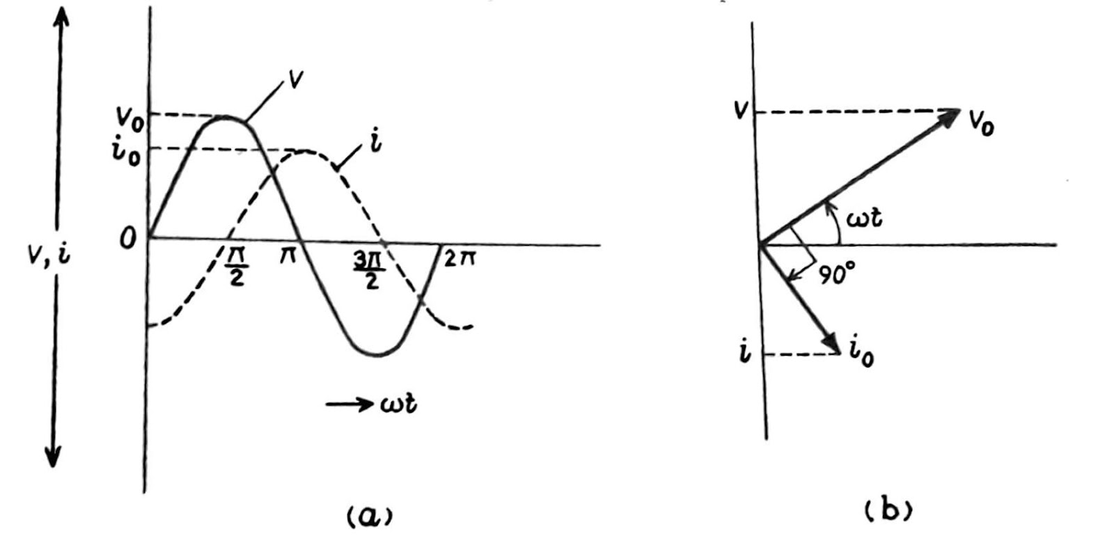
Due to this alternating voltage, the current that flows through the circuit also changes continuously between zero and maximum value and flows in one direction in the first half rotation and in the opposite direction in the next half rotation. This type of current is called an ‘ alternating current’. The alternating current may be expressed as
Where i₀ is the maximum (or peak) value of current.
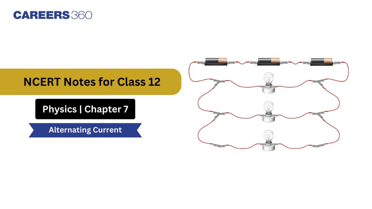
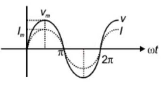
We get a sine curve (as shown in fig) when we plot the graph between the alternating voltage V or alternating current i and time t.
Some Important Terms Regarding The Alternating Current
-
Maximum value or Peak value: In a magnetic field, a coil is rotating, which produces the alternating voltage or current is maximum at two positions of the coil. This maximum value of alternating current or alternating voltage is known as the peak value of voltage or current. As shown in the above fig. It is represented by V₀ or i₀, respectively.
-
Periodic Time: The time taken by the alternating current to complete one cycle is called the periodic time of the current. If in Eqn (i) or (ii), t is increased by 2. The value of V or i remains unchanged. The periodic time of alternating current is
-
Frequency: The number of cycles completed by an alternating current in one second is called the frequency of the current. It is equal to the number of rotations completed by the coil in one second. If the periodic time of the alternating current is T, then its frequency is
Mean Value of An Alternating Current
An alternating current flows during a one-half cycle in one direction and during the other half-cycle in the opposite direction. So, the mean (or average) value of alternating current is zero for one complete cycle.
The mean value of alternating current over a half cycle is a finite quantity and quantity which is defined as the mean value of alternating. It is given by
Thus, the mean value of a.c. for a half-cycle(t = 0 to = T/2) is 0.637 times, or 63.7% of the peak value.
Similarly, the mean value of ac for the other half-cycle will be (t = T/2 to T) will be -2i0/Π=-0.637i0. It is zero for the full cycle.
Root mean square value of alternating current: The root-mean-square value of an alternating current is defined as the square root of the average of i² during a complete cycle, where i is the instantaneous value of the alternating current.
The root mean square of the alternating current is given by
Thus, the root means the square value of an alternating current is 0.707 times and 70.7% of the peak value.
Similarly, the root mean square value of an alternating voltage represented by V = V₀ sin, t is given by
The phase difference between voltage and current i in an alternating current circuit
In some circuits, the current reaches its maximum value before the voltage becomes maximum. Then, it is said the current is leading the voltage in phase. In some other circuits, the current reaches its maximum value after the voltage has become maximum. In such cases, the current is said to be lagging behind the voltage in phase.
If the alternating current circuit the voltage and the currents are in the same phase is that when the voltage is maximum the current is also maximum and when the voltage is zero the current is also zero then the alternating voltage and the alternating current are represented by the following equations
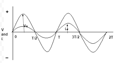
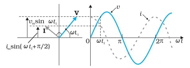
If in an alternating current circuit, the current leads the voltage V by a phase difference ϕ, then the expression for the voltage and the current will be written as follows
The graphical representation is shown in Fig 2.
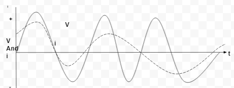
If in a circuit, the alternating current i lags behind the alternating voltage by a phase difference ϕ. Then,
This graphical representation is shown in Fig 3.
Phasors and Phasor diagrams:- The (rotating) vectors representing current and voltage are called phasors.
Phasor diagrams show alternating current and alternating voltage with their phase angles as rotating vectors (phasors).
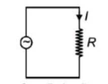
AC Voltage Applied to a Resistor
Let a.c. voltage applied is
Confused between CGPA and Percentage?
Get your results instantly with our calculator!
where
where
Representation of AC Current and Voltage by Rotating Vectors — Phasors
To represent the phase relationship between voltage and current in a.c. circuit, phasor diagram is used. A phasor is a vector which rotates about the origin with angular speed
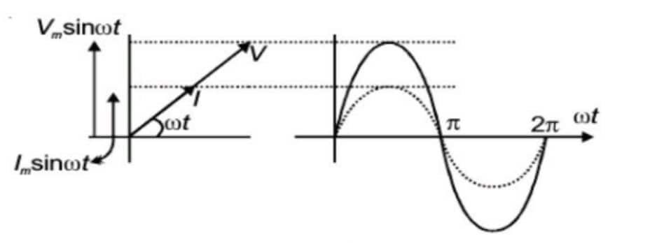
Figure shows the phasor diagram for voltage and current for an a.c. source connected to a resistor.
AC Voltage Applied to an Inductor
Let an alternating voltage is given by
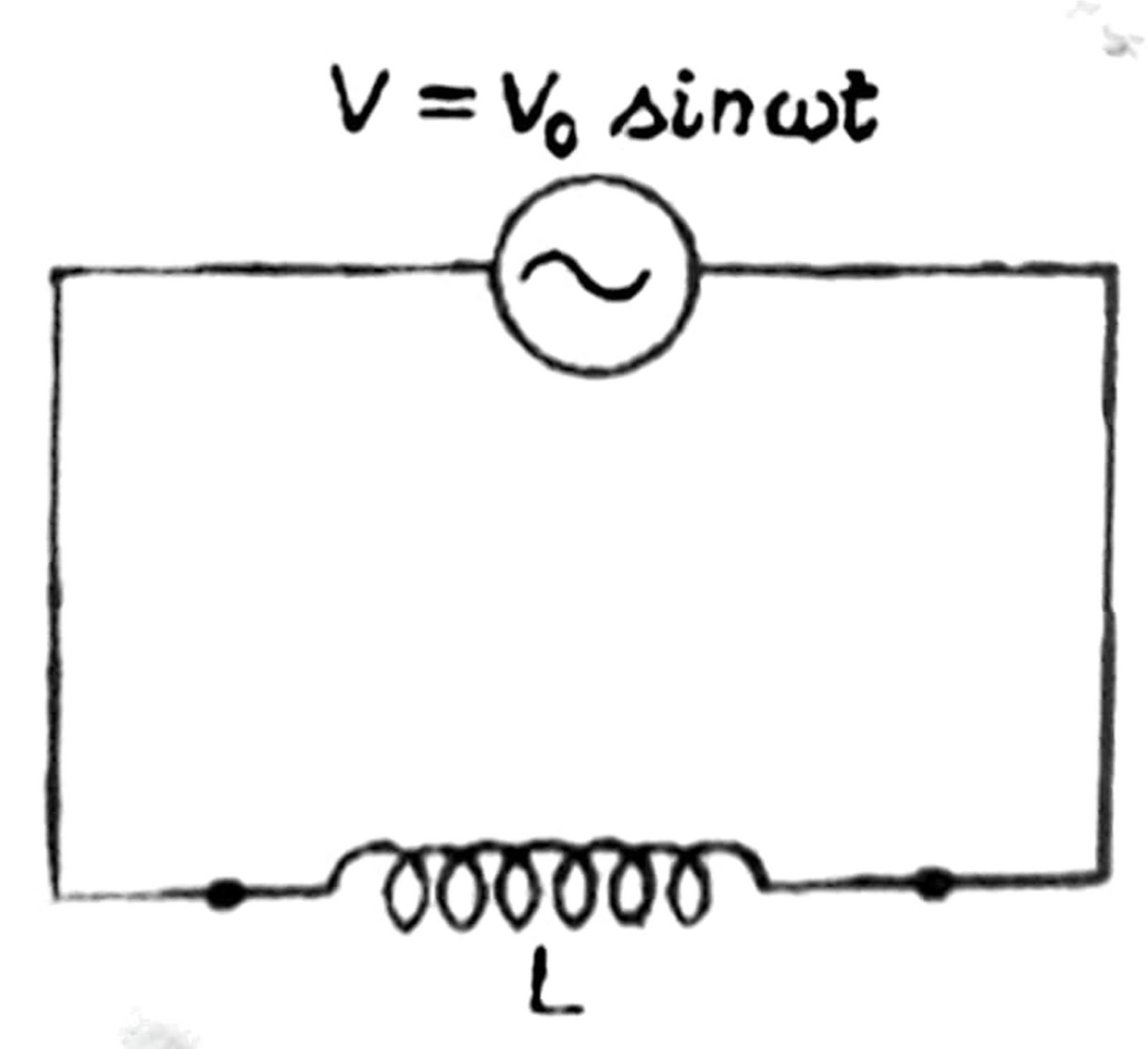
The maximum current in the circuit,
Where i₀ = ( V₀/⍵L) is the peak value of current. Comparison of this equation with the voltage equation shows that in a pure inductor, the current lags behind the voltage by a phase angle. This means that when the voltage is at maximum, the current is zero, and vice versa. Fig 5 (a) shows this phase relationship graphically, and figure 5 (b) shows the phasor diagram AC circuit containing inductance only.
Inductive Reactance (XL) is the opposition offered by an inductor to the flow of alternating current, and it increases with frequency- like how a swing resists sudden pushes!
Formula:
Where:
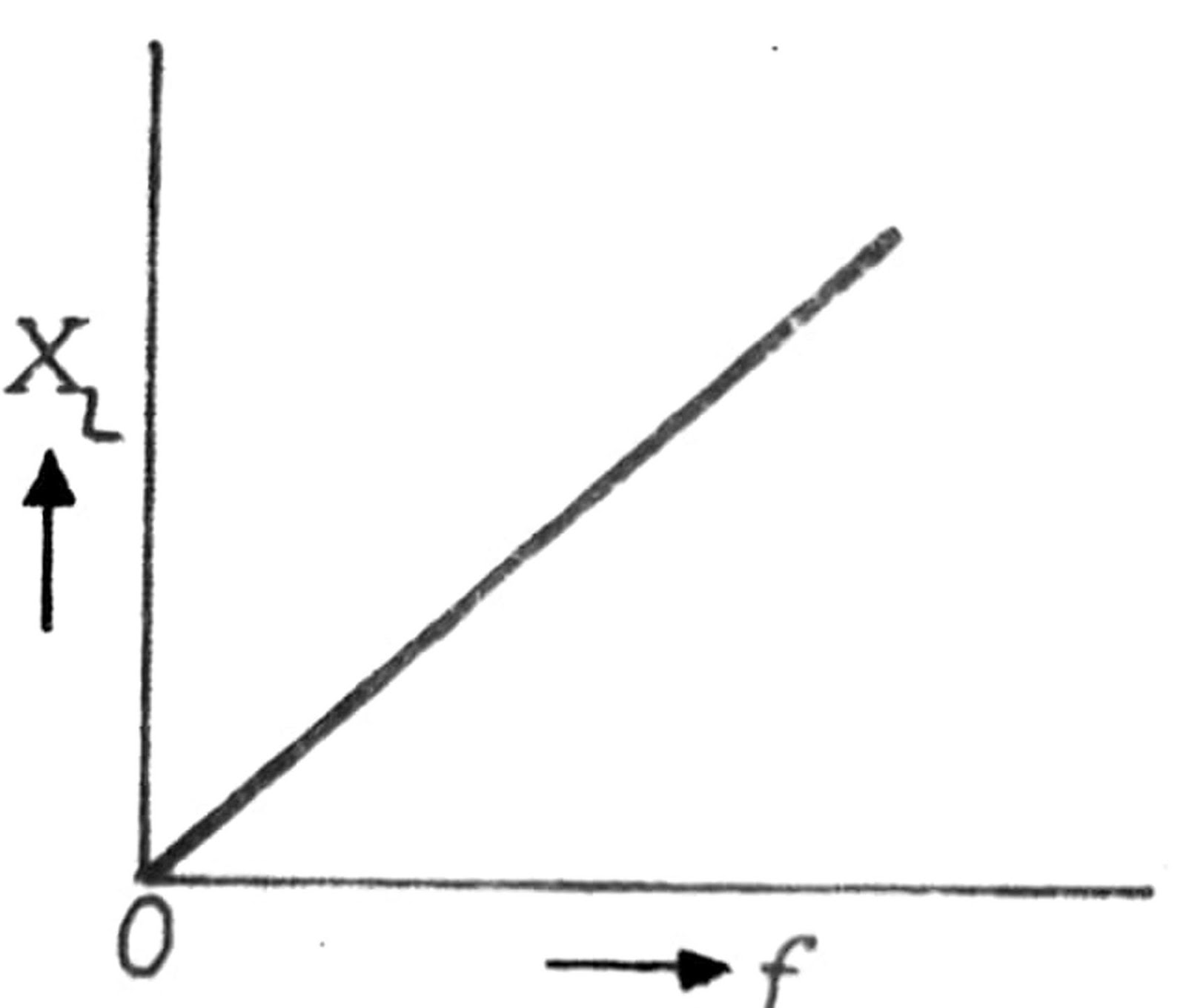
Where f is the frequency of the alternating current. Thus, the inductive reactance increases with the increasing frequency of the current
When L is in henry, F is in hertz, and XL is in ohm.
AC Voltage Applied to a Capacitor
The alternating Voltage is given by
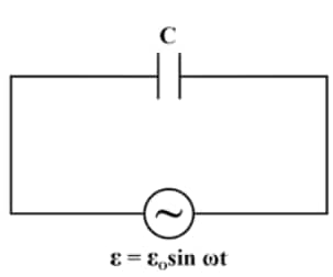
The maximum current in the circuit
Phasor Diagram:
It is clear that the current through a capacitor is ahead of voltage by
Capacitive Reactance (XC) is the opposition offered by a capacitor to the flow of alternating current, and it decreases as the frequency increases, like how a sponge passes water faster when the flow is rapid!
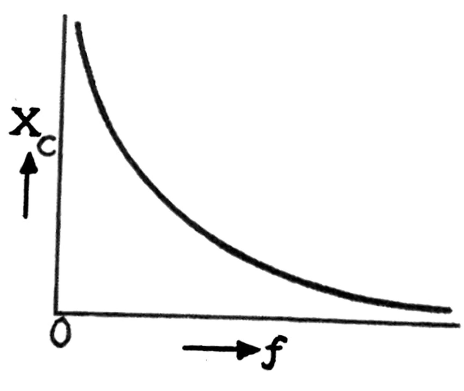
Where:
Circuit containing Inductance and Resistance in series(L-R series circuit).
Let an alternating voltage V=V0sin ,t be applied to a circuit containing an inductance L and a non-inductive resistance R are in series as shown in fig. The same current will flow both in L and R.
Let i be the current in the circuit at any instant and VL and VR. The potential difference across L and R., respectively at that instant. Then


Where XL is the inductive reactance, VR is in phase with the current i, while VL leads i by 90°. Thus, VR and VL are mutually at right angles.
The phasor diagram is drawn in the figure. In this diagram, the vector represents VR while OB represents VL. The vector OD represents the resultant of VR and VL, which is applied voltage V.
According to Ohm's law, a circuit's effective resistance is
We can decode it as Z, which is the impedance of the circuit. Hence, we have the L - R circuit.
But,
The quantity Z is measured in ohm is called impedance because it impedes the flow of alternating current in the circuit. The reciprocal of the impedance is called the admittance of the AC circuit. It is measured in mho or ohm-¹ (Ω-¹) or siemens (S).
The phasor diagram shows in the L - R circuit that the applied voltage V leads the current i (or the current i lags behind the voltage V) by a phase angle ϕ given by
It is clear from the situation that if L = 0, then ϕ = 0( the voltage and the current will be in the same phase): If R = 0, then ϕ = 90° (the voltage will lead the current by 90° ).
v. A circuit containing capacitance and resistance in series:- in this case, the instantaneous potential difference across C and R are given by VC=iXC and VR=iR where XC is the capacitive reactance and i is the instantaneous current.


Now, VR is in the phase with i while VC lags behind i by 90°. The phasor diagram is drawn in the figure in which the vector OA represents VR, and the vector OB represents VC. The vector OD represents the resultant of VR and VC, which is applied voltage V. Thus,
Applying Ohm's law, we see that
is the effective resistance of the circuit. It is called the impedance of the circuit and is represented by Z. Thus, in a C - R circuit, we have
But
The phasor diagram shows that in the C R circuit, the applied voltage V lags behind the current i ( or the current i leads the voltage V) by a phase angle ϕ, given by
AC Voltage Applied to a Series LCR Circuit
Let an alternating voltage V=V0sinωt be applied to a circuit containing an inductance L, a capacitance C, and resistance R all joined in series. As shown in fig. The same current i will flow in all three and the vector sum of the potential difference across them will be equal to the applied voltage.

Let i be the current in the circuit at any instant of time and VL, VC and VR are the potential difference across L, C and R, respectively at that instant. Then
Now XL and XC are the inductive and capacitive reactance, respectively.
Now VR is in phase with i but VL leads by 90°. The phasor diagram is drawn as a figure. In this diagram, the vector OA represents VR and the vector OB represents VL and the vector OC represents VC. VLand VC is opposite to each other. if VL>VC then their results will be VL-VCwhich is represented by OD. Finally, the vector OF represents the resultant of VR and VL-VC, ie., the resultant of all the three, which is applied voltage V. Thus
Applying Ohm's law, we see that
The phasor diagram (fig) shows that in the L-C-R circuit the applied voltage V leads the current i was a phase angle ϕ given by
The following three cases arise
When
When
When
Again when
Which is the minimum value Z can have. Thus, in case, impedance is minimum and hence, the current is maximum. This is the case of electrical resonance. Hence, at resonance
But ω=2πf, where f is the frequency of the applied voltage. Therefore
Where
is the natural frequency of the circuit when the resistance is zero.
The condition for resonance is the frequency of the applied voltage should be equal to the natural frequency of the circuit when the resistance of the circuit is zero.
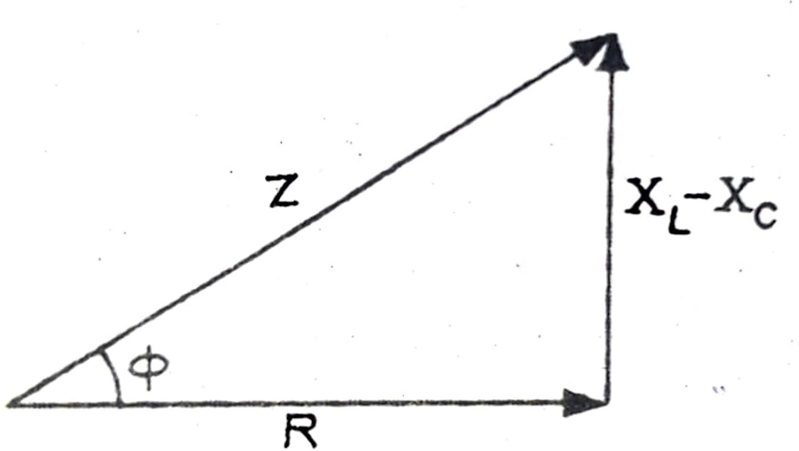
Impedance triangle:- The impedance of an L-C-R a.c. The circuit is given by
and the phase relationship is given by
This triangle is called the impedance triangle.
Power in AC Circuit: The Power Factor
As
(From impedance triangle
The terms cos
Case 1: Circuit containing pure resistance only:-
Case-2 : Purely Inductive or Capacitive Circuits: The phase difference
Case-3 : In an series LCR circuit, power dissipated is given by
where
Case-4 : Power dissipated at resonance in LCR circuit. At resonance
Transformers
It works on the principle of mutual induction. The transformer is a device that is used for converting a large alternating current at low voltage into a small current at high voltage and vice versa. The transformers that convert low voltage into higher ones are called step-up transformers, while those that convert high voltages into lower ones are called step-down transformers
.
Construction: A simple transformer consists of two coils called the primary and the secondary, insulated from each other and bound on a common soft iron laminated core. One of the two coils has a smaller number of turns of thick insulated copper wire cover while the other hand a large number of turns of thin insulated copper wire. In a step-up transformer, the coil of the copper wire has a smaller number of turns in a primary coil and the coil of wire has a large number of turns in the secondary coil (fig a) in the step-down transformer the order is reversed.
Theory:- The given source of EMF says AC mains is always connected to the primary coil. When the alternating current flows through the primary coil, then in each cycle of the current, the core is magnetised once in one direction and once in the opposite direction. Moreover, since the secondary coil is also wound on the same core, the magnetic flux passing through it is subjected to continuous changes as the core is magnetised and de-magnetised again and again. Consequently, alternating EMFs at the same frequency are induced in the secondary coil through mutual induction. Depending on the ratio of turns in the two coils, the secondary coil induces its own EMF.
Let Np and Ns be the number of turns in the primary and secondary coil, respectively. Let us assume that there is no leakage of magnetic flux so that the same flux passes through each turn of the primary and secondary. Let ΦB be the magnetic flux linked with each turn of either coil at any instant. Then by Faraday's law of electromagnetic induction, the EMF induced in the primary coil is given by
The EMF induced in the secondary coil is given by
The induced EMF ep in the primary coil will be nearly equal to the applied voltage Vp across its ends if there is no resistance in the primary circuit and no loss of energy in it. Likewise, if the secondary circuit is open, then the voltage
VS across its and will equal the EMF es induced in it. Under this condition, we have
Where r is called the transformer ratio. In a step-up transformer, r is more than 1, whereas in a step-down transformer r is less than 1. Thus,
If ip and isbe the current in the primary and the secondary at any instant and the energy losses be zero, then
Power in the secondary = power in the primary
When voltage is stepped-up, the current is correspondingly reduced in the same ratio and vice-versa. Thus, the energy obtained from the secondary coil is equal to the energy given to the primary coil.
Alternating Current: Previous Year's Question and Answer
Q1: An inductor of reactance 1Ω and a resistor of 2 Ω are connected in series to the terminals of a 6 V (rms) a.c. source. The power dissipated in the circuit is
(A) 8 W
(B) 12 W
(C) 14.4 W.
(D) 18 W
Answer:
The average power dissipated in the circuit
Hence, the answer is the option 3.
Q2: If the RMS current in a 50 Hz AC circuit is 5 A, the value of the current 1/300 seconds after its value becomes zero is
(A)
(B)
(C)
(D)
Answer :
It is given that
Hence, The answer is the option (2).
Q3: When an AC voltage of 220 V is applied to the capacitor C, then
(A) The maximum voltage between plates is 220 V.
(B) The current is in phase with the applied voltage.
(C) The charge on the plates is in phase with the applied voltage.
(D) Power delivered to the capacitor is zero.
Answer :
The power applied to the circuit is given by
Hence, the answer is the option (4).
Importance of Alternating Current Class 12 Notes
Understanding how Power is Transferred in Circuits
- Study of ac introduces students to active, reactive, and apparent power that enable students to calculate the energy used in a home or industrial plant.
Foundation for Related Advanced Topics
- The knowledge of ac is a must for covering transformers, resonance as it relates to ac circuits, and electromagnetic waves that rely on concepts developed earlier in this chapter.
Foundation for Electrical Engineering Topics
- Most generators and power systems use ac. Students' learning is driven by the applications to situations occurring in real life.
Necessary for Competitive Exams
- Terms like RMS proportions, reactance, phasor diagrams, and reasons for the use of ac circuits often find themselves in tests such as the JEE, NEET, and other engineering/medical tests.
Visual and Analytical Skills
- Using phasor diagrams and waveforms enhances visualization and analytical problem-solving abilities in electrical circuits.
NCERT Class 12 Notes Chapterwise
The chapterwise notes from NCERT Class 12 Physics reduce complex concepts into basic points and aim to make things easier for students. These NCERT Class 12 Physics chapterwise notes consist of all explanations, formulas, diagrams, and solved examples for each every chapter which can be used for revision and concept building among students. These NCERT notes for Class 12 Physics can help students in their board exam preparation as well as JEE/NEET preparation by providing a summary or review of each topic.
|
NCERT Class 12 Physics Chapter 7 Notes |
Subject Wise NCERT Exemplar Solutions
Subject Wise NCERT Solutions
NCERT Books and Syllabus
Frequently Asked Questions (FAQs)
Yes, understanding Alternating Current (AC) class 12th notes is important for JEE preparation as it aligns with the syllabus and provides essential knowledge for tackling physics questions in the exam.
It is one of the important chapters, can expect 4 to 6 marks questions from the chapter alternating Current.
There are some major topics covered in alternating current Class 12 notes, including The Application of AC Voltage to a Resistor, Representating AC Current, and Voltage by Rotating Vectors - Phasors, The Application of AC Voltage to an Inductor, The Application of AC Voltage to a Capacitor, The Application of AC Voltage to a Series LCR Circuit, The Application of AC Voltage to an LCR Circuit, and Power in AC Circuit: The Power Factor
The transformer is a device that is used for converting a large alternating current at low voltage into a small current at high voltage and vice versa.
These topics can also be downloaded from Alternating Current Class 12 notes pdf download.

Popular Questions
A block of mass 0.50 kg is moving with a speed of 2.00 ms-1 on a smooth surface. It strikes another mass of 1.00 kg and then they move together as a single body. The energy loss during the collision is
| Option 1)
|
Option 2)
|
| Option 3)
|
Option 4)
|
An athlete in the olympic games covers a distance of 100 m in 10 s. His kinetic energy can be estimated to be in the range
| Option 1)
|
Option 2)
|
| Option 3)
|
Option 4)
|
A particle is projected at 600 to the horizontal with a kinetic energy . The kinetic energy at the highest point
| Option 1)
|
Option 2)
|
| Option 3)
|
Option 4)
|
In the reaction,
| Option 1)
|
Option 2)
|
| Option 3)
|
Option 4)
|
How many moles of magnesium phosphate, will contain 0.25 mole of oxygen atoms?
| Option 1)
0.02 |
Option 2)
3.125 × 10⁻² |
| Option 3)
1.25 × 10⁻² |
Option 4)
2.5 × 10⁻² |