

NCERT Class 12 Physics Chapter 10 Notes Wave Optics - Download PDF
Have you ever seen the beautiful rainbow patterns on a soap bubble or the colourful designs on an oil film floating on water? These fantastic patterns are not mere coincidences but are due to the wave nature of light, a concept that is explained in NCERT Class 12 Physics Chapter 10 Notes Wave Optics. This chapter opens the concept of light as a wave and the property that gives rise to the unique phenomena of interference, diffraction, and polarisation.
This Story also Contains
- NCERT Class 12 Physics Chapter 10 Notes: Download PDF
- NCERT Class 12 Physics Chapter 10 Notes
- Wave Optics Previous Year Question and Answer
- Importance of NCERT Class 12 Physics Chapter 10 Notes
- NCERT Class 12 Physics Notes Chapterwise
- NCERT Books and Syllabus
NCERT Class 12 Physics Chapter 10 Notes Wave Optics cover all basic concepts, which include Huygens’ Principle, wavefronts, Young’s Double Slit Experiment (YDSE), and polarisation of light. These NCERT notes made by subject experts provide short derivations, formulas ready for exams, well-labelled diagrams, and simplified explanations for making difficult topics manageable. They are compatible with the latest CBSE syllabus and thus also serve as a preparation for various competitive exams like JEE and NEET, where wave optics understanding is a must. Thus, the NCERT Class 12 Physics Chapter 10 Notes PDF is a perfect combination for the students who wish to make a quick revision, strengthen their concepts, and also have solved previous year questions for obtaining accuracy and speed in exams.
Also read,
NCERT Class 12 Physics Chapter 10 Notes: Download PDF
NCERT Class 12 Physics Chapter 10 Notes cover the complete chapter of the wave with very simple and concise explanations of the major topics like Huygens’ principle, interference of light, diffraction, Young’s double slit experiment, and polarisation. The latest CBSE syllabus-based design of this PDF not only contains the important formulas and derivations that are also done, but the diagrams are also there, so that you can prepare for CBSE Class 12 board exams, JEE, and NEET. Take your copy now and enhance your last-minute revision.
NCERT Class 12 Physics Chapter 10 Notes
Wave Optics Class 12 Notes explain the wave nature of light through concepts like interference, diffraction, and polarisation. These well-structured notes make learning easier with clear diagrams, key formulas, and concise explanations, helping students prepare effectively for CBSE board exams, JEE, and NEET.
Wavefront
A light source is a spot that radiates noise in all directions. In a homogeneous medium, the disturbance hits all of the medium's particles in phase, which are all placed at the same distance from the light source, and so every particle must vibrate in phase with each other at all times. A wavefront represents the surface of constant phase in the propagation of a wave.
- The direction of propagation of light is perpendicular to the wavefront.
- The time taken by the light to travel from one wavefront to another is the same along any ray.
- The phase difference between various particles on the wavefront is zero.
Wavefronts can be one of the following sorts, depending on the shape of the light source:
- Spherical WaveFront:
A spherical wavefront is created by a point source of light. This is because the locus of all equidistant points from a point source is a sphere. - Cylindrical WaveFront:
A cylindrical wavefront is produced when the light source is linear (such as a slit). Every equidistant point from the linear source is located on the surface of a cylinder - Plane WaveFront:
If a wavefront is a small component of a spherical or cylindrical wavefront originating from a distant source, it will appear as a plane.

Huygens' Principle
According to the Huygens principle, every point on the given wavefront acts as a source of a new disturbance called secondary wavelets. And a common tangent to these secondary wavelets in the forward direction at any instant gives the new wavefront at that instant, as shown in the figure below. This is called the secondary wavefront.

Properties of Light explained using Huygens' Principle
Light waves follow the Laws of Reflection and Refraction. These can be explained using Huygens' principle.
Refraction of Plane Wave
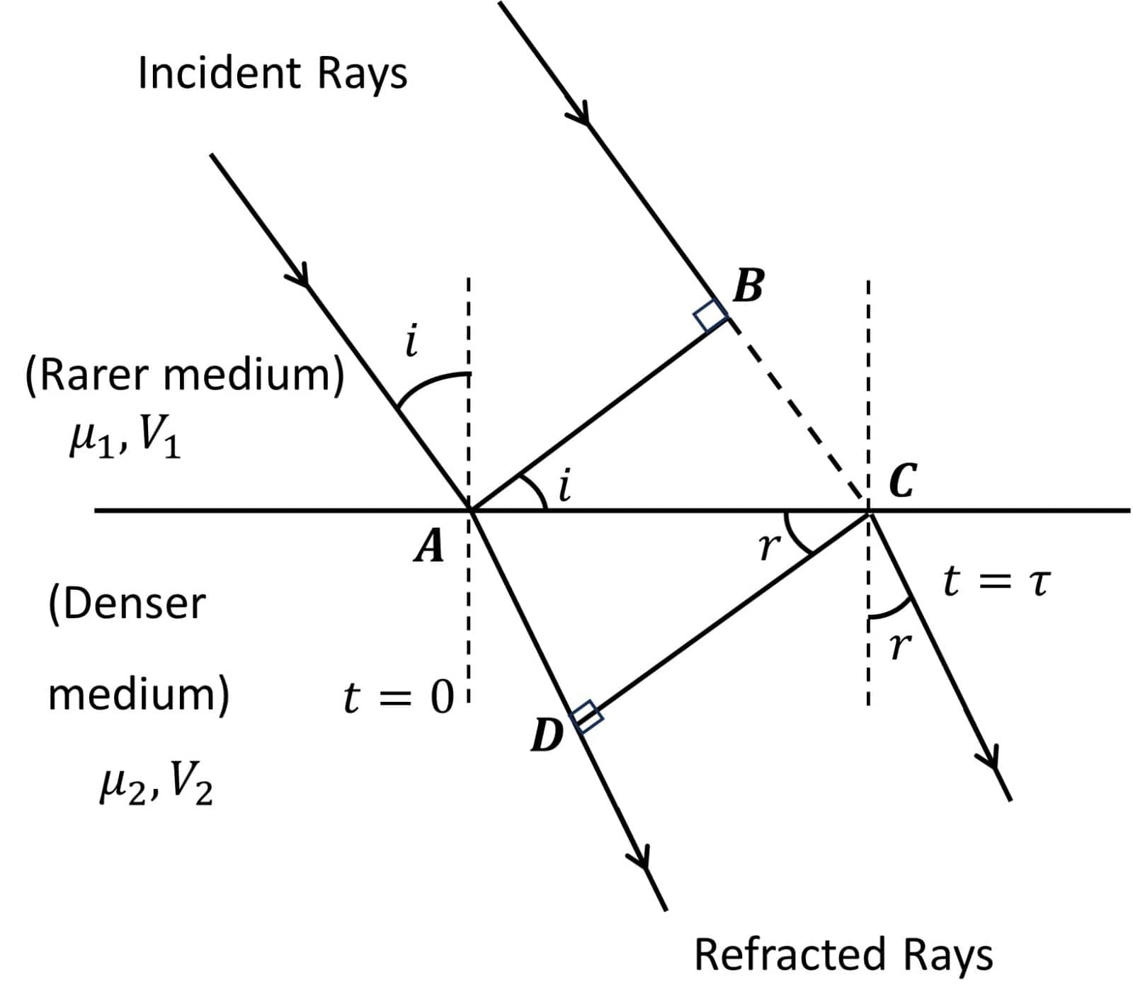
Consider a plane wavefront travelling towards a plane
Let
Let
if
Similarly
For
similarly
For
So we get
And we know
So we get
This verifies the first law of refraction.
Similarly, from the figure, we can say that the incident wavefront, the refracted wavefront and the normal lie in the same plane.
This again verifies the second law of Refraction.
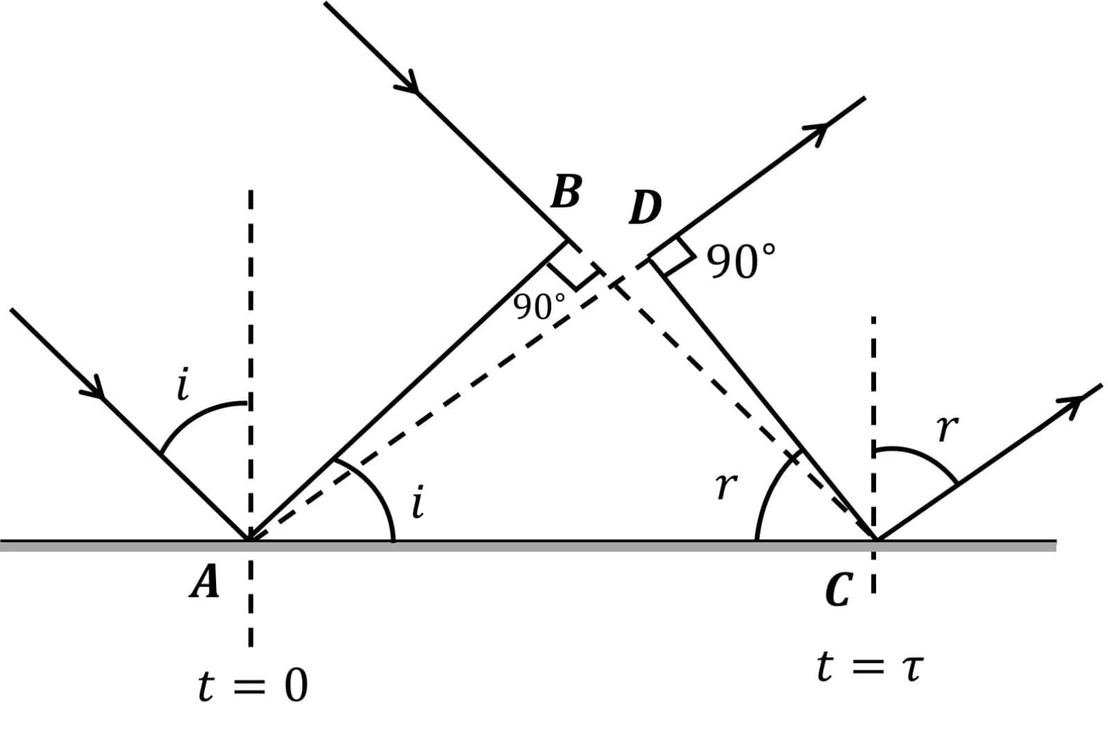
Reflection of Plane Wave
Consider a plane wavefront travelling towards a plane reflecting surface as shown in the figure.
Let
Let at
if
And as
This verifies the first law of reflection, which states that the angle of incidence i and angle of reflection
Similarly, from the figure, we can say that the incident wavefront, the reflected wavefront and the normal lie in the same plane.
This again verifies the second law of reflection.
Therefore, the two laws of Reflection are verified using Huygens's Principle.
Addition of Coherent Waves
Coherent sources of light are light sources that emit continuous light waves of the same wavelength, frequency, and phase (or with a constant phase difference).
Principle of Superposition
Suppose there are two sources of waves

Now, the two waves from
Consider the superposition of two sinusoidal waves of the same frequency (which means sources are coherent) at some point. Let us assume that the two waves are travelling in the same direction with the same velocity. The equation of the two waves reaching a point can be written as
The same relation can be achieved by vector addition of the two amplitudes, with the angle between them equal to the phase difference.

Resultant Intensity
We know,
So, if
For identical sources-
Important Terms for Superposition of Waves
Phase difference (
Path difference (
Time Difference (T.D.): It is the time difference between two waves meeting at a place. =
Constructive Interference
In this condition, the two waves are completely in phase. For this, their path difference must be an integral multiple of the wavelength.
The intensity is,
Destructive Interference
In this condition, the two waves are completely out of phase. For this, their path difference must be an odd multiple of half-wavelength.
The intensity is,
Young’s Double Slit Experiment (YDSE)
When monochromatic light (single wavelength) falls on two narrow slits S1 and S2 that are very close together, they act as two coherent sources, and the waves from these two sources superimpose on each other, an interference pattern appears on the screen. In this experiment, bright and dark bands alternated on the screen. Fringes are the name given to these bands.
d is the distance between the slits.
D be the distance between the slits and the screen.

The path difference between interfering waves that collide at point P on the screen is given by
where y is the position of point P from the central maxima
For maxima at P:
And for minima at P:
Bandwidth
The distance between any two consecutive bright or dark bands is called the bandwidth. For YDSE, this comes out the be a constant value.
Taking the consecutive dark or bright fringe,

Properties of Young's Double Slit Experiment:
-
At the central position Φ=0o or Δ=0 the Central fringe will always be bright
-
A slit's fringe pattern will be brighter than a point's fringe pattern.
-
If the slit widths are mismatched, the minima will not be fully dark. As a result, uniform illumination occurs over a wide area.
-
When one slit is lit with red light and the other with blue light, no interference pattern appears on the screen.
Diffraction of Light
The phenomenon of light bending around the corners of an obstacle/aperture with a size comparable to the wavelength of light is known as Diffraction Of Light
Types of Diffraction
- Fresnel Diffraction
- The source and screen are at a finite distance.
- No lenses are used.
- Wavefronts are spherical or cylindrical.
- The diffraction pattern changes with the distance between the screen and the obstacle.
- Example: Light bending around the edge of a razor blade.
-
Fraunhofer Diffraction
- Source and screen are at infinite distance (or made so with lenses).
- Lenses are used to make the wavefronts plane.
- The diffraction pattern is sharp and fixed.
- Commonly used for studying diffraction in labs.
- Example: Diffraction pattern through a single slit using a laser and lenses.
Single Slit Diffraction
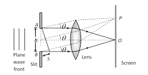
The central maxima in Fraunhofer diffraction by a single slit is the brightest and widest part of the diffraction pattern observed on a screen. When light passes through a narrow slit, it spreads out and forms a series of bright and dark fringes. The central maxima are located at the midpoint directly opposite the slit and are significantly more intense than the subsequent fringes.
(i) The Angular width of the central maxima
(ii) Linear width of central maxima
The secondary maxima are smaller peaks of intensity located on either side of the central maximum.
The secondary minima are the points where the intensity of the diffracted light falls to zero between the central maximum and subsequent maxima.
Comparison Between Interference and Diffraction
|
Interference |
Diffraction |
|
The superposition of waves from two coherent sources produces this effect. |
The superposition of wavelets from different portions of the same wavefront produces this effect. |
|
All fringes are of the same width |
Although all secondary fringes are the same width, the centre maxima is twice as wide. |
|
All fringes have equal intensity |
Intensity decreases as the order of maximum increases. |
|
Path difference for Path difference for |
For Path difference for |
Polarisation
-
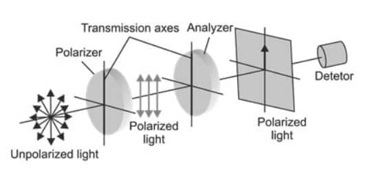
Unpolarized light:
Unpolarized light is light that has electric field oscillations in all directions in a plane perpendicular to its propagation. The horizontal and vertical components of light oscillation are separated.
-
Polarised light:
Plane or polarised light is light that has just one plane of oscillations.
The plane of oscillation is the plane in which polarised light oscillates.
The plane perpendicular to the plane of oscillation is the plane of polarisation.
Light can be polarised by passing through particular crystals like tourmaline or Polaroid..
-
Polaroid:
A Polaroid is the name of the device that produces plane-polarised light. It is based on the selective absorption principle. It's also more powerful than the tourmaline crystal. It is a thin layer of ultramicroscopic quinine iodide sulphate crystals with optic axes parallel to one another.
Only light oscillations that are parallel to the transmission axis can travel through a Polaroid.
Malus Law
The square of the cosine of the angle between the analyser’s plane of transmission and the plane of the polariser will vary the intensity of polarized light passing through an analyzer. This is referred to as Malus's Law.
Brewster’s law
When unpolarized light is reflected from a clear medium (with refractive index=μ), the reflected light will be totally plane-polarised at a specific angle of incidence (known as the angle of polarisation θp). Brewster's law is the name for this rule.
Resolving Power:
If two-point objects are near together, their image diffraction patterns will likewise be close together and overlap.
The minimum distance between two objects that can be seen independently by the object instrument is known as the instrument's limit of resolution.
-
Resolving power of Microscope:
R.P. of microscope =
-
Resolving power of Telescope:
R.P of telescope =
Where D is the aperture of the telescope
Confused between CGPA and Percentage?
Get your results instantly with our calculator!
Wave Optics Previous Year Question and Answer
Q.1 Two coherent light waves of intensity
(a) phase difference between the waves.
(b) resultant intensity at the point.
(c) resultant intensity in terms of the intensity at the maximum
Answer:
a) Phase difference,
b) Resultant Intensity,
c)
Q.2 Write the conditions of path difference under which (i) constructive, (ii) destructive interference occurs in Young’s double-slit experiment.
Answer:
(i) For constructive interference
Path difference should be an even multiple of half a wavelength.
(ii) For destructive interference
Path difference should be an odd multiple of half a wavelength.
Q.3 A beam of plane-polarised light is passed through a polaroid. Show graphically the variation of the intensity of the transmitted light with athe ngle of rotation of the polaroid.
Answer:
The intensity follows Malus' Law,
The graph shows the variation of the intensity (I) of light with the angle of rotation

Importance of NCERT Class 12 Physics Chapter 10 Notes
Strengthens Conceptual Understanding
- Wave Optics Class 12 Notes greatly facilitate learning by presenting the wave nature of light; consequently, students can grasp the complicated topics of interference, diffraction, and polarisation with clarity.
Essential for Board Exams
- Indeed, these notes are prepared according to the NCERT Class 12 Physics syllabus, which makes them indispensable for CBSE board exam preparation. The notes give an account of all the key derivations, formulas, and diagrams that are frequently asked in the exams.
Boosts Competitive Exam Preparation
- Firstly, the most important things for JEE, NEET, and other entrance exams are the concepts from which experiments like Young’s Double-Slit Experiment, Huygens’ Principle, and polarisation of light are derived. Just from these topics, students have to solve various kinds of problems to hone their skills further.
Simplified Diagrams and Derivations
- Class 12 Physics Wave Optics notes prepare the students for their exams with the help of easy-to-follow step-wise derivations and well-labelled diagrams.
Time-Saving Revision Tool
- In fact, these NCERT Class 12 Physics Chapter 10 Notes can be very helpful for students to do a quick last-minute revision; thus, they can utilise this time to check if every topic has been covered before exams.
Helps in Visual Learning
- Just to name a few, the illustrations of wavefronts, light propagation, and interference patterns provided in these notes are perfect examples of difficult concepts getting simplified for the student's better retention.
Free and Accessible PDF
- The availability of the Wave Optics Class 12 Notes PDF free download allows students to study at their convenience, thus making the learning process flexible and comfortable.
NCERT Class 12 Physics Notes Chapterwise
NCERT Class 12 Physics Notes chapter-wise are available for quick learning and revision in a well-structured and concise manner. These notes consist of all the essential concepts, formulas, and diagrams according to the latest CBSE syllabus; thus, they are ideal for board exams, JEE, NEET, and other competitive exams. Moreover, with the chapter-wise PDF links, you can conduct revision offline at your convenience.
|
NCERT Class 12 Physics Chapter 10 Notes |
Subject Wise NCERT Exemplar Solutions
- NCERT Exemplar Class 12 Solutions
- NCERT Exemplar Class 12 Maths
- NCERT Exemplar Class 12 Physics
- NCERT Exemplar Class 12 Chemistry
- NCERT Exemplar Class 12 Biology
Subject Wise NCERT Solutions
NCERT Books and Syllabus
Frequently Asked Questions (FAQs)
Wavefront is the locus of all points of a wave which are in the same phase. Rays denote the direction of propagation of light in a single direction. It is a straight line path. This is direction is perpendicular to the surface of the wavefront.
The necessary condition for diffraction to occur is that the barrier size must be comparable to the wavelength of the wave. Sound waves have a wavelength of the order of a few meters and centimetres. Since objects of that size are more common, diffraction is more noticeable by us.
Polarization is used in sunglasses to reduce the Sun's glare, LCD screens, digital communication, spectroscopy and even astronomy.
Diffraction is the phenomenon of bending light waves around the edges of a barrier or opening. These phenomena can occur in almost every wave type. This occurrence is possible, according to the Huygens-Fresnel Principle and the principle of superposition of waves. The Huygens-Fresnel Principle states that every point on a wavefront is a wavelet's source. These wavelets scatter out in a forward direction equal to the speed of the originating wave.
Furthermore, the wavelets' tangent line is a new wavefront. At the same time, the concept of superposition states that the sum of incentives at any instant is the net outcome of numerous stimuli.
Yes, Wave Optics Class 12 notes are important for JEE preparation as they cover essential topics aligned with the JEE syllabus, helping students to grasp key concepts and excel in the exam.

Popular Questions
A block of mass 0.50 kg is moving with a speed of 2.00 ms-1 on a smooth surface. It strikes another mass of 1.00 kg and then they move together as a single body. The energy loss during the collision is
| Option 1)
|
Option 2)
|
| Option 3)
|
Option 4)
|
An athlete in the olympic games covers a distance of 100 m in 10 s. His kinetic energy can be estimated to be in the range
| Option 1)
|
Option 2)
|
| Option 3)
|
Option 4)
|
A particle is projected at 600 to the horizontal with a kinetic energy . The kinetic energy at the highest point
| Option 1)
|
Option 2)
|
| Option 3)
|
Option 4)
|
In the reaction,
| Option 1)
|
Option 2)
|
| Option 3)
|
Option 4)
|
How many moles of magnesium phosphate, will contain 0.25 mole of oxygen atoms?
| Option 1)
0.02 |
Option 2)
3.125 × 10⁻² |
| Option 3)
1.25 × 10⁻² |
Option 4)
2.5 × 10⁻² |