Have you ever thought about how electric current really flows through wires ,and then keeps everyday stuff running like bulbs, fans, and even those mobile chargers? Class 12 Physics Chapter 3 Current Electricity tries to make this feel less confusing by covering the basic ideas of current and circuits in a way that is simpler (and sort of organized, even if it sometimes feels “too clean” in the textbook).
This Story also Contains
NCERT Solutions for Class 12 Physics Chapter 3 - Current Electricity: Download PDF
Physics NCERT Solutions for Class 12 Chapter 3 - Current Electricity: Exercise Question
NCERT Solutions for Class 12 Physics Chapter 3 - Current Electricity: Additional Questions
Class 12 Physics NCERT Chapter 3: Higher Order Thinking Skills (HOTS) Questions
NCERT Class 12 Physics Chapter 3 - Current Electricity: Important Topics
NCERT Physics Class 12 Chapter 3 - Current Electricity: Important Formulas
Approach to Solve Questions of Class 12 Physics Chapter 3 - Current Electricity
How Can NCERT Solutions for Class 12 Physics Chapter 3 Current Electricity Help in Exam Preparation?
Importance of NCERT Solutions for Class 12 Physics Chapter 3: Current Electricity
What Extra Should Students Study Beyond NCERT for JEE/NEET?
Class 12 Physics NCERT Solutions: Chapter- Wise
Current Electricity
In this article, students can find complete NCERT Solutions for Chapter 3, made according to the latest CBSE syllabus. It brings together all the key parts like electric current, Ohm’s Law, resistance, resistivity, drift velocity, electrical power, internal resistance, Kirchhoff’s laws, and the Wheatstone bridge. Besides the theory section, there are step-by-step answers for every NCERT exercise question, plus extra practice problems and HOTS questions so the concepts stick properly, not just for the exam day. This guide also includes handy formulas, a few numerical tricks, and exam-focused tips that improve both accuracy and speed. So whether you’re getting ready for CBSE board exams or competitive exams like JEE and NEET, this article should help you build solid understanding and raise your confidence when solving circuit-based numericals.
NCERT Solutions for Class 12 Physics Chapter 3 - Current Electricity: Download PDF
The Class 12 Physics Chapter 3 - Current Electricity question answers PDF can be downloaded freely, and thus exam preparation will be easy and more organised. Using NCERT Current Electricity Class 12 Solutions PDF, students are able to update stepwise solutions, practice numerical problems and go through key additional and HOTS questions any time and even without internet access. The downloadable class 12 physics chapter 3 Current Electricity questions answers, which are designed by subject experts, are a good study material for both CBSE board exams and regular JEE and NEET students.
Aakash iACST – NEET Repeater
Register for iACST. Get instant Scholarship on NEET Repeater Courses.
Physics NCERT Solutions for Class 12 Chapter 3 - Current Electricity: Exercise Question
The Current Electricity NCERT Solutions of Exercise Questions give step-by-step solutions to all the textbook problems, and even the difficult numerical problems were simplified. Such class 12 physics chapter 3 Current Electricity question answers not only add value to conceptual clarity but also help to increase both the speed and accuracy of problem-solving. They provide well-structured procedures and correct solutions that make them a good practice guide towards board examination of the CBSE and competitive exams such as JEE and NEET.
Given the emf of the battery, $\mathrm{E}=12 \mathrm{~V}$
Internal resistance of battery, r=0.4 Ohm
Let I be the maximum current drawn from the battery.
We know, according to Ohm's law
Given the emf of the battery, $\mathrm{E}=10 \mathrm{~V}$
The internal resistance of the battery, $\mathrm{r}=30 \mathrm{hm}$
Current in the circuit, $\mathrm{I}=0.5 \mathrm{~A}$
Let $R$ be the resistance of the resistor.
Therefore, according to Ohm's law:
For the given voltage, the two values of current will correspond to two different values of resistance, which will correspond to two different temperatures.
V = 230 V
$I_1= 3.2 A$ and $I_2 = 2.8 A$
Using Ohm's law:
$R_1 = 230/3.2 = 71.87\Omega$
and
$R_2= 230/2.8 = 82.14 \Omega$
$T_1= 27^\circ C$
Let $T_2$ be the steady temperature of the heating element.
Emf of battery, $\mathrm{E}=8 \mathrm{~V}$
Internal resistance of battery, $r=0.5 \Omega$
Supply Voltage, $\mathrm{V}=120 \mathrm{~V}$
The resistance of the resistor, $R=15.5 \Omega$
Let V ' be the effective voltage in the circuit.
Now, $\mathrm{V}^{\prime}=\mathrm{V}-\mathrm{E}$
$\implies I = \frac{112}{15.5 + 0.5} = 7 A$
Now, using Ohm's Law:
Voltage across resistor $R$ is $v=I R$
$
V=7 \times 15.5=108.5 \mathrm{~V}
$
Now, the voltage supplied, $\mathrm{V}=$ Terminal voltage of battery +V
\$therefore\$ Terminal voltage of battery $=120-108.5=11.5 \mathrm{~V}$
The purpose of having a series resistor is to limit the current drawn from the supply.
vd :drift Velocity = length of wire(l) / time taken to cover
$I = neA \frac{l}{t}$
by substituting the given values
$\implies$ t = 2.7 x 10⁴ s
Therefore, the time required by an electron to drift from one end of a wire to its other end is $2.7\times 10^4$ s.
NCERT Solutions for Class 12 Physics Chapter 3 - Current Electricity: Additional Questions
The Current Electricity NCERT Solutions of Class 12 Physics are meant to be used in addition to the textbook exercises and are aimed at giving an extra practice on the topic to be understood further. Such questions challenge the reasoning, formula application, and clarity of concepts, and the students are exam-ready. With a regular solution, learners will be able to further prepare themselves to not only board exams but also entrance tests such as JEE and NEET.
(a) Alloys of metals usually have greater resistivity than that of their constituent metals.
(b) Alloys usually have much lower temperature coefficients of resistance than pure metals.
(c) The resistivity of the alloy manganin is nearly independent of temperature.
(d) The resistivity of a typical insulator (e.g., amber) is greater than that of a metal by a factor of the order of $10^{22}$.
This expression is expressed in terms of 1, 2 and 3. Hence, we can make a circuit that consists only of 1 ohm, 2 ohms and 3 ohms and whose equivalent resistance is 11/3. that is :
It can be seen that in every small loop resistor 1 ohm is in series with another 1 ohm resistor, and two 2-ohm resistors are also in series, and we have 4 loops.
The equivalent resistance of one loop is equal to the parallel combination of 2 ohms and 4 ohm that is
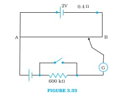
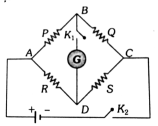
If a sufficiently high current passes through the galvanometer, then it can get damaged. So we limit the current by adding a high resistance of 600 k $\Omega$.
No, the Balance point is not affected by high resistance. High resistance limits the current to the galvanometer wire. The balance point is obtained by moving the joystick on the potentiometer wire, and the current through the potentiometer wire is constant. The balance point is the point at which the current through the galvanometer becomes zero. The only duty of the high resistance is to supply a limited, constant current to the potentiometer wire.
No, the method would not have worked if the driver cell of the potentiometer had an emf of 1.0V instead of 2, because when the emf of the driving point is less than that of the other cell, there won't be any balance point in the wire.
No, the circuit would not work properly for a very low order of Voltage because the balance points would be near point A, and there would be a greater percentage error in measuring it. If we add a series resistance with wire AB. It will increase the potential difference of wire AB, which will lead to a decrease in percentage error.
Class 12 Physics NCERT Chapter 3: Higher Order Thinking Skills (HOTS) Questions
The Class 12 Physics Chapter 3 HOTS (Higher Order Thinking Skills) questions on Current Electricity are designed to test deep conceptual understanding and analytical thinking. These questions go beyond direct textbook problems, encouraging students to apply concepts like Ohm’s Law, Kirchhoff’s Laws, and electrical circuits in new situations. Solving these helps students strengthen logical reasoning, improve problem-solving accuracy, and prepare effectively for competitive exams like JEE and NEET.
Q.1 The total current supplied to the circuit by the battery is
Answer:
The equivalent circuit is
The total resistance of the circuit is
$1.5+\frac{2 \times 6}{2+6}$ in parallel with $3 \Omega$
$\therefore$ Total resistance is $\frac{3}{2}=1.5 \Omega$
Current in the circuit $=\frac{6}{1.5}=4 \mathrm{~A}$
Q.2 What should be the value of E for which the galvanometer shows no deflection?
Answer:
If there is no current in G, as the potential difference across $10 \Omega$ resistance is equal to 10 V, then
Q.3 A circuit consists of five identical conductors as shown in the figure. The two similar conductors are added as indicated by the dotted lines. The ratio of resistances before and after addition will be:
Answer:
Before addition,
Total resistance of the circuit is $\mathrm{R}_1=5 \Omega$
After the addition of the two conductors, the circuit will acquire the form shown in the figure
It is a balanced Wheatstone bridge. The resistance of the central conductor is ineffective.
$\therefore$ Total resistance of the circuit is
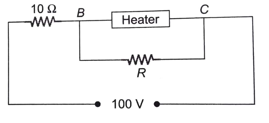
Q.4 A heater is designed to operate with a power of 1000 W in a 100 V line. It is connected in combination with a resistance of $10 \Omega$ and a resistance $R$, to a 100 V mains as shown in figure. For the heater to operate at 62.5 W , the value of R should be $\_\_\_\_$ $\Omega$.
Q.5 In the network shown in the figure below, the potential difference between A and B is Answer:
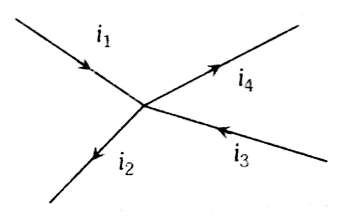
The distribution of current is shown in Fig. Keeping in view that the inflow and outflow of current in a cell must be the same. Applying the loop rule to left and right loops.
💡 Conversion Formula used is: CGPA = Percentage / 9.5
NCERT Class 12 Physics Chapter 3 - Current Electricity: Important Topics
Class 12 Physics Chapter 3 Current Electricity focuses on understanding how electric current flows in conductors and the factors affecting it. This chapter covers key topics like Ohm’s Law, resistance, resistivity, electric power, and combinations of resistors. Learning these concepts helps students build a strong base for both board exams and competitive exams such as JEE and NEET, where circuit-based questions are common.
NCERT Physics Class 12 Chapter 3 - Current Electricity: Important Formulas
Class 12 Physics Chapter 3 Current Electricity includes several important formulas that help in solving circuit-related numerical problems. These formulas cover concepts like Ohm’s Law, resistors in series and parallel, electric power, and Kirchhoff’s laws. Understanding and applying these formulas correctly helps students solve questions quickly and accurately in board exams as well as competitive exams.
Current density:
1. $d i=J d A \cos \theta=\vec{J} \cdot d \vec{A}$
Where: is the angle between the normal to the area and the direction of the current
2. Relation between current density and electric field-
$\vec{J}=\sigma \vec{E}=\frac{\vec{E}}{\rho}$
where = conductivity and = resistivity or specific resistance of the substance
Ohm’s Law:
$\begin{aligned} & V \propto I \\ & V=I R\end{aligned}$
Resistivity:
$\rho=\frac{m}{n e^2 \tau}$
Where:
m is the mass, n is the number of electrons per unit volume, e is the charge of the electron and is the relaxation time
Approach to Solve Questions of Class 12 Physics Chapter 3 - Current Electricity
Solving questions from Class 12 Physics NCERT Chapter 3 Current Electricity requires a logical application of Ohm's Law, Kirchhoff's Laws, and resistor combinations. Instead of memorising, students should focus on understanding the flow of current and applying formulas strategically. A structured approach helps in solving numericals faster and with higher accuracy.
1. Know What Current Is:
Current is simply the flow of electric charge, such as water in a pipe. It flows due to a push named voltage.
2. Learn Ohm's Law(V=IR):
This states $V=I R$ (Voltage $=$ Current $\\times$ Resistance). It's the most important formula - used in the majority of questions.
3. Know About Resistance and Drift of Electrons
Electrons travel slowly in a wire - slow movement is referred to as drift. Resistance is determined by the material, length, and thickness of the wire.
4. Energy and Power:
Understand how to calculate energy and power consumed by devices such as bulbs or fans. Utilize formulas such as $P=$ $V I$ and $E=P t$.
5. Cells and EMF (Voltage):
Real batteries lose some energy within. That's internal resistance. Learn how to calculate total voltage with cells in series or parallel.
6. Kirchhoff's Rules:
These rules assist you in solving circuit problems. One is the current at junctions rule, and the other is the voltage in loops rule.
7. Wheatstone Bridge:
If the bridge is balanced, you can directly use a simple ratio formula to easily determine the unknown resistance.
8. Practice NCERT Questions:
All questions of the board exam are based on the NCERT book mostly. Attempt all examples and exercises. Practice a few previous years' papers also.
How Can NCERT Solutions for Class 12 Physics Chapter 3 Current Electricity Help in Exam Preparation?
NCERT Solutions for Class 12 Physics Chapter 3 - Current Electricity help students develop a clear and logical understanding of how electric current flows through conductors and circuits. These Current Electricity Class 12 NCERT Solutions have made the explanations of the main concepts, including Ohm's law, resistance, resistivity, drift velocity, Kirchhoff's laws, and electrical power, simpler in a series of explanations. Through the practice of numericals and derivations based on Current Electricity Class 12 Questions and Answers, students will become confident enough with solving circuit-related problems in series and parallel combinations, Wheatstone bridge, and meter bridge that are generally tested in CBSE board examinations, JEE, and NEET. With repeated application of these solutions, accuracy is enhanced, frequent errors regarding the use of units and sign conventions are minimised, and problem-solving speed is enhanced. This concentrated study also provides a good base for the subsequent chapters, such as Moving Charges and Magnetism and Electromagnetic Induction, which guarantees improved exam scores.
Importance of NCERT Solutions for Class 12 Physics Chapter 3: Current Electricity
NCERT Solutions for Class 12 Physics Chapter 3 - Current Electricity play a vital role in helping students master one of the most numerically-intensive chapters of Class 12 Physics. This chapter prepares the groundwork for the knowledge of electric circuits and the flow of current.
Helps students gain a clear insight into fundamental concepts such as electric current, the law of Ohm, resistance, and resistivity.
Explains important laws such as Kirchhoff's laws with proper reasoning and step-by-step solutions.
Improves problem-solving with series and parallel combinations of circuits using detailed circuit-based numericals.
Very crucial in CBSE board exams, whereby questions on derivations and numbericals in this chapter are often given.
Highly useful for competitive exams like JEE and NEET, as current electricity forms the base for many higher-level questions.
Helps students avoid common mistakes related to units, sign conventions, and circuit analysis.
Prepares a good groundwork in the next chapters, like in Moving Charges and Magnetism and Electromagnetic Induction.
Illinois Tech Mumbai
Admissions open for UG & PG programs at Illinois Tech Mumbai
What Extra Should Students Study Beyond NCERT for JEE/NEET?
Class 12 Physics Chapter 3 - Current Electricity deals with the fundamental principles, such as Ohm's law, resistivity, combinations of resistors, Kirchhoff's rules, and the Wheatstone bridge. Nevertheless, in the case of JEE and NEET, students must not just use the textbook but concentrate on the higher-order applications like circuit solving with Kirchhoff's laws, network theorems, variations of Wheatstone bridges, and problems which involve the dependency of resistance on temperature. The main way to master this chapter to compete in exams is to practice difficult numerical problems and learn the real-life application of circuits.
The NCERT Class 12 Physics Solutions are compiled in a chapter-wise format to make learning and revision simple. Each chapter link provides step-by-step solutions to textbook exercises, additional questions, HOTS, and key formulas. With these well-structured resources, students can prepare effectively for CBSE board exams as well as competitive exams like JEE and NEET.
NCERT Books and the NCERT Syllabus for Class 12 form the foundation of board exam preparation and competitive exam readiness. Easy access to these links helps students follow the latest curriculum, understand topic-wise weightage, and prepare systematically for CBSE board examinations.
NCERT Solutions subject-wise links provide easy access to chapter-wise answers for all major subjects in one place. These solutions help students understand concepts clearly, practise textbook questions effectively, and prepare confidently for exams
Q: How important is the NCERT Solutions for Class 12 Physics chapter 3 for CBSE board exam?
A:
In CBSE board exam, around 8 to 10% questions can be expected from the chapter Current Electricity. Certain papers of CBSE ask around 15% questions from NCERT chapter 3 Current Electricity. To score well in the exam follow NCERT syllabus and the exercise given in the NCERT Book. To practice more problems can refer to NCERT exemplar.
Q: According to the NCERT Solutions for Current Electricity, what distinguishes resistivity from resistance?
A:
Resistance (R) varies with size and geometry: R = ρ(l/A), where ρ is resistivity, l is length, and A is cross-sectional area. Resistivity (ρ) is a material attribute that describes how strongly a material opposes current flow and is independent of the dimensions of the conductor. For a material, it stays constant at a specific temperature.
Q: What is the weightage of current electricity in JEE main?
A:
In JEE main, 2 to 3 questions can be expected from the chapter on Current Electricity. The topics like Potentiometer, meter bridge, KVL and KCL are important.
Q: Whether NCERT is enough to cover Current Electricity for NEET?
A:
The concepts in the current electricity chapter of NCERT Class 12 Physics are integral parts of NEET exam. Along with NCERT, practicing with previous year papers and mock tests would be enough.
Q: What is the weightage of current electricity for NEET exam?
A:
Current electricity carries 8% of weightage on an average for NEET exam.
Q: How important is the NCERT Solutions for Class 12 Physics chapter 3 for higher studies in the field of engineering?
A:
Current electricity is the basics of electrical and electronics engineering-related branches. In these branches, analysis and designs of the circuit are important and the basic laws studied in the Class 12 Physics Chapter 3 NCERT solutions help for the same.
Q: In Chapter 3 NCERT Solutions, how are complex circuit problems solved using Kirchhoff's Laws?
A:
When it comes to multi-loop and bridge circuits, where basic series/parallel laws do not apply, Kirchhoff's Laws—the Current Law (KCL) and the Voltage Law (KVL)—allow students to construct equations for electrical quantities. By following these rules, students can:
Create simultaneous equations.
Determine unknown voltages and currents.
Examine the circuits that are included in the advanced NCERT and board exam problems.
Q: How can I score well in Current Electricity for my exams?
A:
Focus on understanding the key concepts, practising numerical problems, and solving previous year questions. Refer to NCERT solutions for detailed explanations and practice regularly.
Q: What are Kirchhoff’s laws, and why are they important?
A:
Kirchhoff’s laws — Current Law (KCL) and Voltage Law (KVL) — help in analyzing complex electrical circuits. These laws are crucial for solving circuit problems, especially in JEE and NEET exams.
Q: What is the significance of the Wheatstone Bridge and the Potentiometer?
A:
The Wheatstone Bridge and Potentiometer are important for measuring resistance and EMF in electrical circuits. They have a high weightage in competitive exams like JEE Main and NEET.
A block of mass 0.50 kg is moving with a speed of 2.00 ms-1 on a smooth surface. It strikes another mass of 1.00 kg and then they move together as a single body. The energy loss during the collision is
A person trying to lose weight by burning fat lifts a mass of 10 kg upto a height of 1 m 1000 times. Assume that the potential energy lost each time he lowers the mass is dissipated. How much fat will he use up considering the work done only when
A pulley of radius 2 m is rotated about its axis by a force F = (20t - 5t2) newton (where t is measured in seconds) applied tangentially. If the moment of inertia of the pulley about its axis of rotation is 10 kg m2 , the