

NCERT Class 12 Physics Chapter 9 Notes Ray Optics and Optical Instruments - Download PDF
Have you ever looked at yourself in a mirror or used a camera to take a wide-angle picture and then wondered how it is that it works? Light rays in mirrors and lenses reflect and bend the light to produce images that we can see and capture. NCERT Class 12 Physics Chapter 9 Notes Ray Optics and Optical Instruments come with the detailed study of such mind-boggling concepts.
This Story also Contains
- NCERT Class 12 Physics Chapter 9 Notes: Download PDF
- NCERT Class 12 Physics Chapter 9 Notes
- Ray Optics and Optical Instruments: Previous Year Questions and Answers
- Importance of Ray Optics and Optical Instruments Class 12 Notes
- NCERT Notes for Class 12 Chapterwise
- NCERT Books and Syllabus
These NCERT Class 12 Physics Chapter 9 Notes Ray Optics and Optical Instruments deal with the laws of reflection and refraction, spherical mirrors, Snell’s law, and different kinds of lenses. The chapter further includes the phenomena of total internal reflection, apparent depth, and refraction through a prism, along with the basic concepts. These ideas are the stepping stones for understanding the operation of microscopes, telescopes, cameras, and other optical gadgets, which are part of our daily lives. NCERT Class 12 Physics Chapter 9 Notes PDF is a product of the hard work of the teachers who have given their best to provide detailed explanations, stepwise derivations, well-labelled diagrams and all the important formulas. These NCERT notes play a very important role in preparation for CBSE board exams, JEE, NEET, and other entrance tests, and thus help in revising quickly and efficiently.
See Also,
NCERT Class 12 Physics Chapter 9 Notes: Download PDF
The NCERT Class 12 Physics Chapter 9 Notes in the form of a PDF file dealing with the topics of ray optics and optical instruments is a handy study material that demystifies the fundamental concepts of light reflection and refraction, inverted and convex lenses, glass prisms, and optical devices. Having organised the free PDF with essential formulae, figures, and brief explanations, it is very helpful for revisiting quickly and getting ready for exams.
NCERT Class 12 Physics Chapter 9 Notes
NCERT Class 12 Physics Chapter 9 Notes are an understandable guide to light propagation through reflection and refraction. These notes encompass the essential concepts of spherical mirrors, lenses, prisms, total internal reflection, and optical instruments that make the students capable of preparing their exams effectively.
Introduction
-
In the chapter Ray Optics and Optical Instruments, we will learn about light and try to understand some important phenomena related to light and applications of optics in different optical instruments like microscopes, telescopes etc.
-
We will learn that the phenomenon of laws of reflection and refraction plays an important part in our day-to-day life.
-
With the help of light, we see all the objects around us.
-
Also, we will understand that certain objects enhance the properties of light more as compared to others.
What is Light?
-
We know that light is a form of energy that enables us to see things around us.
-
Light is known to travel in a straight path.
Properties of Light
(i) Speed of light in vacuum, denoted by c, is equal to
(ii) Light is an electromagnetic wave (proposed by Maxwell). It consists of a varying electric field and a magnetic field.

(iii) Light carries energy and momentum.
(iv) The formula
Reflection of Light
When light rays strike the boundary of two media, such as air and glass, a part of the light is turned back into the same medium. This is called the Reflection of Light.
(a) Regular Reflection:
When the reflection takes place from a perfect plane surface, it is called Regular Reflection. In this case, the reflected light has a large intensity in one direction and a negligibly small intensity in other directions.

(b) Diffused Reflection
When the surface is rough, we do not get a regular behaviour of light. Although at each point light ray gets reflected irrespective of the overall nature of the surface, a difference is observed because even in a narrow beam of light, there are many rays which are reflected from different points of the surface, and it is quite possible that these rays may move in different directions due to the irregularity of the surface. This process enables us to see an object from any position.
Such a reflection is called diffused reflection.
For example, reflection from a wall, from a newspaper etc. This is why you can not see your face in the newspaper and on the wall.

Laws of Reflection

(i) The incident ray, the reflected ray and the normal at the point of incidence all lie in the same plane.
(ii) The angle of incidence is equal to the angle of reflection. That is
Note: - These laws are valid at each point on any reflecting surface, whether it is a plane or curved surface.
Reflection of Light by Spherical Mirrors
-
A spherical mirror is a part of a reflective spherical surface and they are spherical in shape.
-
It is a combination of a large number of extremely small plane mirrors.
Type of Spherical Mirror
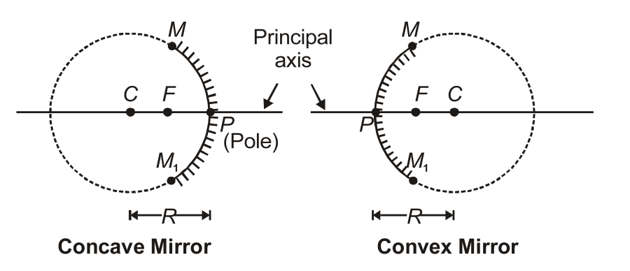
Concave Mirror: -
-
They are silvered on the inner side of the sphere.
-
It is a converging mirror.
-
In a Concave mirror, the reflected rays meet or converge at a point and are known as converging mirrors.
Convex Mirror: -
-
They are silvered on the outer side of the sphere.
-
In a Convex mirror, the reflected rays don’t meet at a point after reflection and are known as diverging mirrors.
Some terminologies related to Spherical Mirrors:-
Pole:
The centre of the reflective surface of a spherical mirror is known as the pole. It lies on the surface of the mirror. It is represented by the letter P.
Centre of curvature:
Centre of the sphere of the reflecting part of the mirror. It is represented by the letter C.
Radius of curvature:
Radius of the sphere. Represented by R.
Principal axis:
The straight line that passes through the pole and the centre of curvature of a spherical mirror is known as the Principal axis. The principal axis is perpendicular to the mirror at its pole.
Principal Focus:
It is the point on the principal axis that rays parallel to the principal axis after reflection pass or appear to pass through. The principal focus is represented by F.
Focal Length
It is the distance between the pole and the principal focus of a spherical mirror; it is considered to be the focal length of the spherical mirror. It is represented by f.
Aperture:
In a spherical mirror, the diameter of the reflecting surface is known as the aperture.
For mirrors with a smaller aperture than their radius of curvature, we use R=2f
Sign Convections
-
We take the pole (P) of the mirror as the origin. The principal axis of the mirror is considered to be the x-axis (X’X) of the coordinate system.
-
We consider the object to be placed to the left of the mirror. We assume that the light from the object always falls on the mirror from the left-hand side of the mirror.
-
We measure all the distances that are parallel to the principal axis from the pole of the mirror.
-
We measure all the distances to the right of the origin (along + x-axis) and take them as positive, while those measured to the left of the origin (along – x-axis) are taken as negative.
-
Distances that are measured perpendicular to and above the principal axis (along + y-axis) are taken as positive, whereas those which are measured along (-y-axis) are taken as negative.
-
The heights that are measured upwards with respect to the x-axis and normal to the principal axis (x-axis) of the mirror/ lens are considered to be positive. The heights that are measured downwards are taken to be negative.
-
We take the radius of curvature and the focal length of a concave mirror to be negative, and those for a convex mirror are positive.
Mirror Formula
Where:-
u is the distance of the object measured from its pole
v is the distance of the image measured from the pole of the mirror
f is the distance of the principal focus measured from the pole
The mirror equation gives the relation between the image distance (v), with object distance (u), and the focal length (f) of the mirror.
Magnification of a Spherical Mirror
Magnification
Reflection at Spherical Mirror (Laws of Image Formation):
1. A ray initially parallel to the principal axis and close to it, after reflection, passes or appears to pass through the principal focus.
(from law of reflection i.e.,

2. A ray initially passing or appearing to pass through the principal focus, after reflection, becomes parallel to the principal axis (by the principle of reversibility i.e., after any number of reflections, if the direction of the light ray is reversed, it retraces its whole path).

3. A ray initially passing or appearing to pass through the centre of curvature, after reflection, retraces its path.

Image Formation by a Spherical Mirror
Below are the properties of the image formed by spherical mirrors when objects are kept at different distances
Image Formation by a Concave Mirror:

Image Formation by a Convex Mirror:

Important Points about Spherical Mirrors
You should remember the following important points while dealing with spherical mirrors.
(i) As an object is held in front of a spherical mirror, the distance of the object
(ii) The real image is formed in front of the mirror. So its distance
(iii) The virtual image is formed at the back of the mirror. So its distance
(iv) The focal length of concave mirror is considered as negative.
(v) Focal length of convex mirror is considered as positive.
(vi) When image formed is virtual and erect, magnification is positive.
(vii) When image formed is real and inverted, magnification is negative.
(viii) The height of the object is taken to be positive as the object is usually placed above the principal axis.
(ix) The height of the image should be taken as positive for virtual images while it is taken as negative for real images.
Uses of Spherical Mirrors
A concave mirror is used:
(i) As a reflector in search lights, the headlights of motor vehicles produce powerful parallel beams of light. It is also used in telescope, solar cookers etc.
(ii) In an ophthalmoscope for reflecting light onto the retina of the eye.
(iii) As a shaving mirror, a make-up mirror, as it can form an erect and magnified image.
(iv) By dentists to see large images of the teeth of patients.
A convex mirror is used:
As a rear-view mirror in automobiles (like cars, trucks and buses) to see the traffic behind. Such a mirror is preferred because it has a much wider field of view as compared to a plane mirror or a concave mirror and always produces an erect image.
Refraction of Light
Refraction is the phenomenon in which the direction of propagation of light changes (as shown in the figure) when it passes from one transparent medium to another. This is because the speed of light is different in different media.

Laws of refraction
-
The incident ray, the refracted ray and the normal to the interface all lie together at the point of incidence, in the same plane.
-
The ratio of the sine of the angle of incidence to the sine of the angle of refraction is constant. This is known as Snell's Law.

This constant value
Conditions for no refraction:
1. If light is incident normally on a boundary
From Snell's law

So, the light ray in the second medium will pass undeviated at the boundary.
2. If the refractive indices of two media are equal

From Snell's law,
So, a light ray in the second medium will pass undeviated at the boundary.
Refraction through a parallel slab
When light passes through a parallel slab, having the same medium on both sides, then
(a) The emergent ray is parallel to the incident ray.
(b) Light is shifted laterally, given by (students should be able to derive it)

Real Depth and Apparent Depth
If a coin is placed in a glass of water, it will appear to be raised. Due to refraction, objects in an optically denser medium appear to be raised. This is called the apparent depth of the object.

Here, O is the real position of the object, and O' is the apparent position of the object as seen by the observer. h is the real depth of the object from the surface of the water, and h' is the apparent depth of the object.
Total Internal Reflection
When light travels from an optically denser medium to a rarer medium at the interface, it is partly reflected into the same medium and partly refracted into the second medium. This reflection is known as internal reflection.
In total internal reflection, there is no refraction and the entire incident ray will be reflected.

-
When a ray of light passes from a denser medium to a rarer medium, it always bends away from the normal.
-
But if we increase the angle of incidenc,e it will move from normal and the angle of refraction will become less.
-
Now, if we keep on increasing the angle of incidence, the angle of refraction will become equal to 90o and with a further increase in the angle of incidence, there will be no refraction, but reflection will take place. This is total internal reflection.
The conditions for total internal reflection are:-
-
The angle of incidence should be greater than the angle of incidence for which the angle of refraction is 90o. The angle of incidence should be greater than the critical angle.
Optical Fibres
-
They are used in the telecommunications industry.
-
Optical fibres work on the phenomenon of total internal reflection.
Characteristics of Optical Fibres:
-
They are small in size and light in weight. They can carry more information than metallic wires.
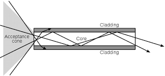
Working of Optical fibres:
-
Optical fibres are fabricated with high-quality composite glass/quartz fibres.
-
Each fibre consists of a core and cladding, due to which the refractive index of the material of the core is higher.
-
The signal has repeated total internal reflections along the length of the fibre. It finally comes out at the other end, when a signal is in the form of light. It is directed at one end of the fibre at a suitable angle.
-
The light undergoes total internal reflection at each stage. There is no loss in the intensity of the light signal.
-
Optical fibres are fabricated in such a way that the light reflected at one side of the inner surface strikes the other at an angle larger than the critical angle.
-
Light can easily travel along its length if the fibre is bent. An optical fibre can be used to act as an optical pipe and is made up of plastic.
Glass vs. Plastic Optical Fibres
|
Plastic Optical fibres |
Glass Optical fibres |
|
1. Cheaper |
They are not so cheap. |
|
2. Flexible |
They are not so flexible. |
|
3. They can withstand more stress. |
They cannot withstand more stress. |
|
4. Less efficient transmission. |
More efficient transmission over large distances. |
Applications of Optical Fibres
- Fibre optic endoscopy
- Decorative items
- In a communication system
- Prism
Refraction at Spherical Surfaces and by Lenses
Refraction at a spherical surface is a fundamental concept in optics, where light rays change direction as they pass through the boundary between two different media with varying refractive indices. Unlike plane surfaces, spherical surfaces can converge or diverge light rays, leading to the formation of real or virtual images.
Refraction at Spherical Surfaces
Let us consider refraction at a spherical interface between two transparent media. An infinitesimal part of a spherical surface can be regarded as planar. The same laws of refraction are applicable at every point on the surface.

If an object 0 is placed in front of a curved surface as shown in the above figure, then the Refraction formula is given as
where
and
and u = Distance of object, v = Distance of image, R = Radius of curvature
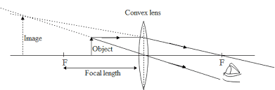
Refraction by Lens: Convex & Concave
-
A ray of light incident on the lens parallel to the principal axis after refraction passes through the second principal axis.
-
A ray of light passing through the first principal focus after refraction should move parallel to the principal axis.
-
A ray of light passing through the optical centre goes undeviated after refraction.
Lens Maker’s Formula
The Lens Maker's formula is given as-
Here, f is the focal length, n is the refractive index, R1 and R2 are the radii of curvature of the two refracting surfaces of the lens.
Lens Formula
As we have a formula for spherical mirrors, we also have a formula for spherical lenses. This formula gives the relationship between object-distance (
Magnification of a Lens
-
Magnification is defined as the ratio of the size of the image to the size of the object.
-
It is denoted as m= h'/h=v/u
Power of a Lens
Power
The SI unit of power of a lens is 'dioptre' and is denoted by the letter D.
Combination of Thin Lenses in Contact
If a number of lenses are combined (or placed adjacent and touching each other) to increase the magnification, then the net power of the combination
As
Refraction Through a Prism
Prism is a transparent optical material with flat, polished surfaces that refracts light.

Dispersion: It is the separation of light into its constituent colours.
Spectrum: When light undergoes dispersion, the band of colours obtained is calleda spectrum.
The band of colours obtained with the white light is violet, indigo, blue, green, yellow, orange and red (VIBGYOR).
Incident Ray: - The ray entering the prism.
Refracted Ray: - The ray coming out of the prism inside the prism.
Emergent Ray: - The ray coming out of the prism.
The angle of deviation δ:-The angle showing the deviation of the emergent ray from the original incident ray.
The angle of Prism: - The angle of prism ∠A is known as the angle of prism.
-
With the increase in the angle of incidence, the angle of deviation decreases. When it reaches a point where the angle of incidence is equal to the angle of emergence, the angle of deviation is minimum, and again it will start decreasing.
Angle of Deviation

where
Condition for Minimum Deviation
For minimum deviation
(i) Refracted ray becomes parallel to the base of the prism.
(ii) Angle of incidence becomes equal to the angle of emergence. i.e.,
Hence minimum angle of deviation

Critical Angle
It is the angle of incidence in denser medium corresponding to which the angle of refraction in rarer medium is
where,
Optical Instruments
-
Optical instruments are the instruments that use the reflecting and refracting properties of mirrors, lenses and prisms.
-
A number of optical devices and instruments use reflecting and refracting properties of mirrors, lenses and prisms.
-
Some examples of optical devices and instruments are a periscope, a kaleidoscope, binoculars, telescopes, and microscopes
Some examples of optical instruments consisting of lenses and prisms are mentioned below:-
- Binoculars
- Telescope
- Microscopes
- Eye
Microscope
The microscope is an instrument that gives an enlarged image of a minute object.
There are 2 types of the microscope:-
-
Simple
-
Compound
Simple Microscope
It is an instrument that gives an enlarged image of a minute object.
-
The lens is held near the object and the eye is positioned close to the lens on the other side.
-
The image that we get is erect, magnified and virtual at a distance so that it can be viewed comfortably, i.e., at 25 cm or more.
To Increase the Magnifying Power of a Simple Microscope
-
If the object is at a distance ‘f’, the image will be formed at infinity. If the object is at a distance slightly less than the focal length of the lens in that case the image is virtual and closer than infinity.
-
The closest comfortable distance for viewing the image is when it is at the near point at a distance D≅25cm. But it causes some strain on the eye.
-
Therefore, we consider the image formed at infinity to be the most suitable for viewing by the eye.
We can acquire linear magnification ‘m’, for the image shaped at the close to purpose D, by an easy magnifier by the relation:-
m=v/u=v(1/v-1/f)
= 1-(v/f)
Using the sign conventions, v = (-) ive and same as D.
Therefore, magnification will be m=1+(D/f)
D is 25 cm, so in order to have a magnification of six, one needs a convex lens of focal length, f = 5 cm.
Magnification When The Image is at Infinity-
Suppose the object has a height h. The maximum angle subtended and clearly visible without a lens is at a distance D.
The angle subtended is then given by:-
tanθ0=h/D≈θ0
Therefore, h/'h=m=v/u
The angle subtended by the image will be:-
tanθ1=h'/(-v)= [h/(-v)][v/u]
= h/(-u)≈θ
When the object is at u, the angle subtended by it is (-f).
θi= h/f
The angular magnification is m=θi/θ0=D/f
m =(θi/θ0) =(D/f)
Compound Microscope
In order to have large magnifications, a compound microscope is used.
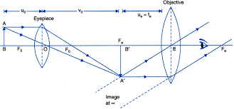
The lens that is nearest to the object is known as the objective. It forms a real, inverted, magnified image of the object. This acts as the object for the second lens, known as the eyepiece. It acts like a simple microscope or magnifier, producing the final image, which is enlarged and virtual.
The first inverted image is near the focal plane of the eyepiece. The final image is inverted.
Using tanβ=h/f0=h'/L
Magnification (mo) due to objective =h'/h=L/f0
Where
h’ = size of the first image
h = size of the object
f0 = focal length of the objective lens
fe= focal length of the eye-piece
L = Distance between the focal length of the second objective lens and the first focal length of the eyepiece.
-
If the final image is formed at the near point, then in that case the angular magnification will be:-
me=1+D/fe
-
If the final image is formed at infinity, then, in that case, angular magnification due to the eyepiece is:-
me=D/fe
Total magnification will be given as:-
m=m0me=(L/f0)(D/fe)
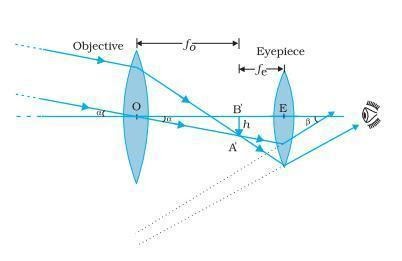
Telescope
A telescope is an instrument used to view distant objects clearly.
It consists of
(a) Objective lens
(b) Eyepiece
Working of the Telescope
We use the telescope for angular magnification of distant objects. The objective lens has a large focal length and a much larger aperture than the eyepiece, as the object is very far away.
Light from a distant object enters the objective and a real and inverted image is formed at its second focal point.
This image acts as an object for the eyepiece and it magnifies this image, producing a final inverted image.
Magnification
The magnifying power ‘m’ is nothing but the ratio of the angle β subtended at the eye by the final image to the angle α that is subtended by the object at the lens or the eye.
Therefore, m≈β/α=(h/fe)(f0/h)=f0/fe
In this case, the length of the telescope tube is f0+ fe.
We use refracting telescopes for both terrestrial and astronomical observations.
Confused between CGPA and Percentage?
Get your results instantly with our calculator!
Ray Optics and Optical Instruments: Previous Year Questions and Answers
Q.1 A beam of light converges at a point P. Now, a convex lens is placed in the path of the convergent beam at 15 cm from P. At what point does a beam converge if the convex lens has a focal length 10 cm?
Answer:

Hence, the beam will converge 6 cm from the lens.
Q.2 The focal length of an equiconcave lens is
Answer:
If the lens is immersed in a medium with a refractive index greater than 5/3, it will behave like a converging lens.
Q.3 An astronomical telescope has an objective lens of focal length 20 m and an eyepiece of focal length 1 cm.
(i) Find the angular magnification of the telescope.
(ii) If this telescope is used to view the Moon, find the diameter of the image formed by the objective lens. Given the diameter of the Moon is
Answer:
i)
ii)
Importance of Ray Optics and Optical Instruments Class 12 Notes
Strong Concept Clarity
- These NCERT Class 12 Physics Chapter 9 Notes make the topics of reflection, refraction, and total internal reflection, that is the most complicated ones, understandable in a very simple way.
Exam-Oriented Preparation
- The notes cater to the requirements of CBSE Class 12 Board Exams by giving brief explanations, offering key formulas, and providing solved examples.
Competitive Exam Advantage
- The knowledge of JEE, NEET, and other entrance exams significantly depends on the understanding of concepts like lenses, prisms, microscopes, and telescopes, and these notes make it easier for students to get these topics at a glance.
Quick Revision Tool
- The well-organised Ray Optics and Optical Instruments Class 12 Notes help students to do the revision of the laws and derivations very quickly, thus they become very handy before the exams.
Visual Understanding
- The notes mention the diagrams and ray diagrams for easing conceptual understanding and further retention of concepts.
Important Derivations Included
- The derivations on the basis of the mirror formula, lens formula, and optical instruments are being done stepwise, thus learning becomes easy and effective.
Application-Based Learning
- The students get the practical use of Ray Optics in optical devices through these notes, which improves the connection between theory and real-life applications.
NCERT Notes for Class 12 Chapterwise
The NCERT Notes for Class 12 Chapterwise are essentially a chapterwise class 12 notes that offer a comprehensive summary of the entire syllabus. This is a complete set of notes made from NCERT books with the sole purpose of helping students get through their school exams in the quickest way possible and, at the same time, ensure that they get good marks.
|
NCERT Class 12 Physics Chapter 9 Notes |
Subject Wise NCERT Exemplar Solutions
- NCERT Exemplar Class 12 Solutions
- NCERT Exemplar Class 12 Maths
- NCERT Exemplar Class 12 Physics
- NCERT Exemplar Class 12 Chemistry
- NCERT Exemplar Class 12 Biology
Subject Wise NCERT Solutions
NCERT Books and Syllabus
Frequently Asked Questions (FAQs)
The key topics covered include- image formation by spherical mirrors and lenses and its properties. Phenomena such as total internal reflection and dispersion by prisms are also covered. Finally, optical instruments and devices such as optical fibres, microscopes and telescopes are discussed.
Numericals of Ray Optics and Optical Instruments are based on either curved mirrors or lenses. For mirror, use the mirror formula along with magnification. For lenses, it is important to note the Lens Maker's formula and the Lens formula. Keeping the sign convention in mind is important and must be correctly applied in the required places. Along with this, noting the results of optical devices such as microscope and telescope is also important.
Optical fibres consist of thin and long strands of fine quality glass or quartz coated with a thin layer of material of refractive index less than the refractive index of strands. They work on the principle of total internal reflection so they do not suffer any loss.
Uses:
The optical fibres are used in medical investigations i.e. one can examine the inside view of the stomach and intestine by a method called endoscopy.
Yes, understanding Ray Optics and Optical Instruments Class 12 notes is crucial for NEET as it covers topics relevant to optics, which are frequently tested in the physics section of the exam
The focal length of a lens for red light will be larger than that for blue light.

Popular Questions
A block of mass 0.50 kg is moving with a speed of 2.00 ms-1 on a smooth surface. It strikes another mass of 1.00 kg and then they move together as a single body. The energy loss during the collision is
| Option 1)
|
Option 2)
|
| Option 3)
|
Option 4)
|
An athlete in the olympic games covers a distance of 100 m in 10 s. His kinetic energy can be estimated to be in the range
| Option 1)
|
Option 2)
|
| Option 3)
|
Option 4)
|
A particle is projected at 600 to the horizontal with a kinetic energy . The kinetic energy at the highest point
| Option 1)
|
Option 2)
|
| Option 3)
|
Option 4)
|
In the reaction,
| Option 1)
|
Option 2)
|
| Option 3)
|
Option 4)
|
How many moles of magnesium phosphate, will contain 0.25 mole of oxygen atoms?
| Option 1)
0.02 |
Option 2)
3.125 × 10⁻² |
| Option 3)
1.25 × 10⁻² |
Option 4)
2.5 × 10⁻² |