Mathematics Of Electrical Circuits: Analysing Current, Voltage, And Resistance
Electrical circuits are the backbone of modern technology, powering everything from our homes to the vast network of devices we rely on daily. Whether it's charging your smartphone, operating household appliances, or even running a sophisticated industrial system, all of these functions are made possible by the intricate interplay of current, voltage, and resistance in electrical circuits.
This Story also Contains
- Key Components Of Electrical Circuits
- Fundamental Principles: Ohm's Law And Kirchhoff's Laws
- Analysing Circuits: Series And Parallel
- Electrical Power

Class 12 marks a crucial stage in your academic journey, where you delve deeper into the concepts of physics and mathematics. As you explore the world of electrical circuits, you will realise that mathematics plays a pivotal role in comprehending and analysing their behaviour. By understanding the mathematical principles governing electrical circuits, you will be able to make accurate predictions, troubleshoot problems, and design efficient circuits.
Today, we will cover the key components of electrical circuits, including resistors, capacitors, and inductors. We will examine Ohm's Law, Kirchhoff's Laws, and other fundamental principles that govern the behaviour of these components. You will learn how to calculate current, voltage, and resistance in series and parallel circuits, as well as more complex configurations.
As we explore the mathematical principles, we will also provide practical insights into circuit analysis, using circuit diagrams and mathematical models. By leveraging the power of mathematical equations and techniques, you will be able to analyse circuits and calculate unknown quantities such as current voltage, resistance, and maximum power.
Whether you are a Class 12 student or if you plan to pursue a career in engineering, or physics, or simply want to develop a deeper understanding of the world around you, the knowledge gained from this guide will be helpful throughout the whole journey. So, continue to read the article to get a deeper insight into the concepts.
Key Components Of Electrical Circuits
To understand electrical circuits comprehensively, we must familiarise ourselves with their key components. These include resistors, capacitors, and inductors. Each component plays a unique role in shaping the behaviour of the circuit. Let's take a closer look at these components:
Resistors
Resistors are fundamental components that regulate the flow of electric current in a circuit. They offer resistance to the flow of electrons, thereby controlling the amount of current passing through the circuit. The resistance is measured in ohms (Ω) and is a critical parameter in circuit analysis.
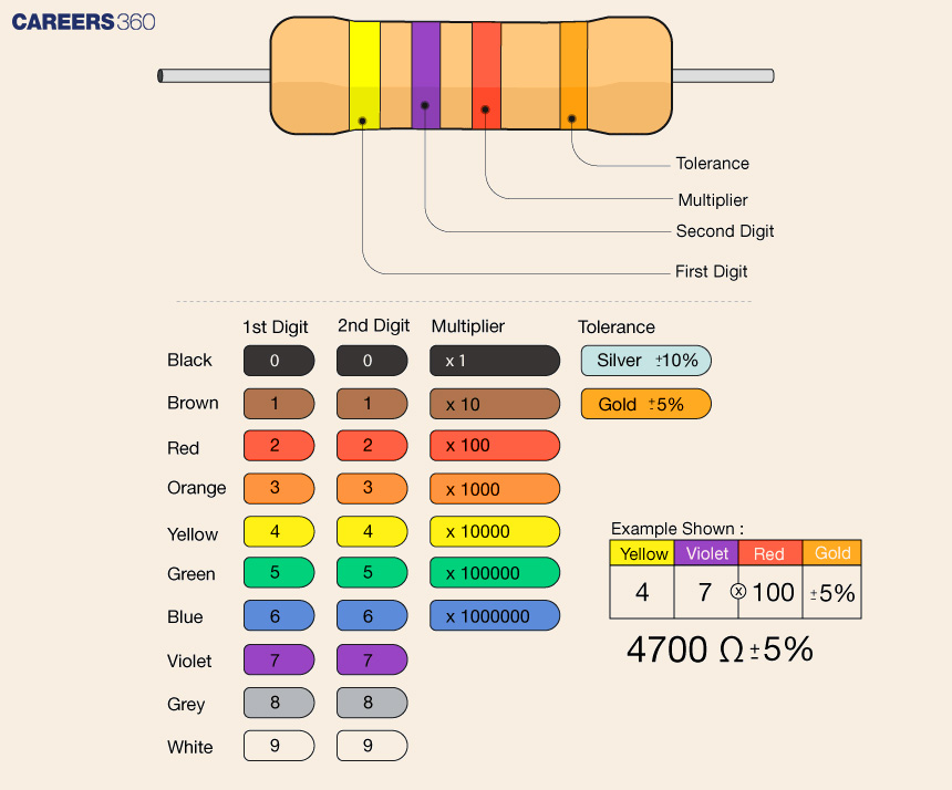
Here, the colour code gives you an insight into resistance.
Capacitors
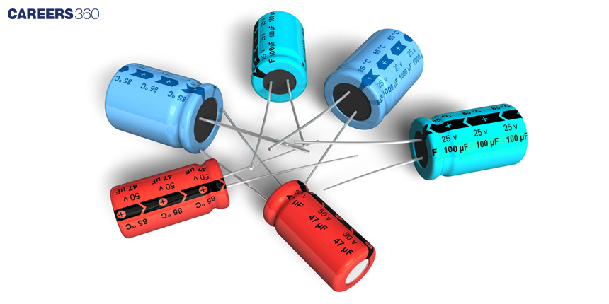
Capacitors store electrical energy in the form of an electric field. They consist of two conductive plates separated by an insulating material, and their capacity to store charge is measured in farads (F). Capacitors play a vital role in filtering signals, smoothing voltage fluctuations, and providing energy for certain circuit operations.
Inductors
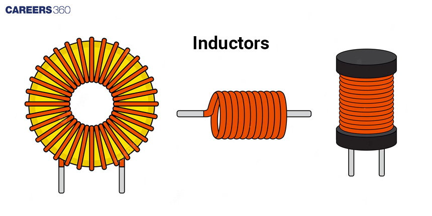
Inductors, also known as coils or solenoids, store electrical energy in the form of a magnetic field. They resist changes in current flow and are characterised by their inductance, measured in henries (H). Inductors are crucial in applications involving electromagnetic fields and can be found in transformers, motors, and generators.
Fundamental Principles: Ohm's Law And Kirchhoff's Laws
To analyse and understand electrical circuits, we need to grasp a few fundamental principles. Two key principles that govern the behaviour of electrical circuits are Ohm's Law and Kirchhoff's Laws.
Ohm's Law
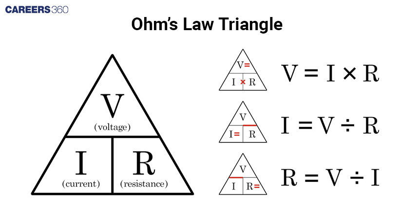
Ohm's Law states that the current flowing through a conductor is directly proportional to the voltage applied across it and inversely proportional to its resistance. This law can be mathematically expressed as I = V/R, where I represents current in amperes (A), V represents voltage in volts (V), and R represents the resistance in ohms (Ω). The law can be visualised using the following image.
Kirchhoff's Laws
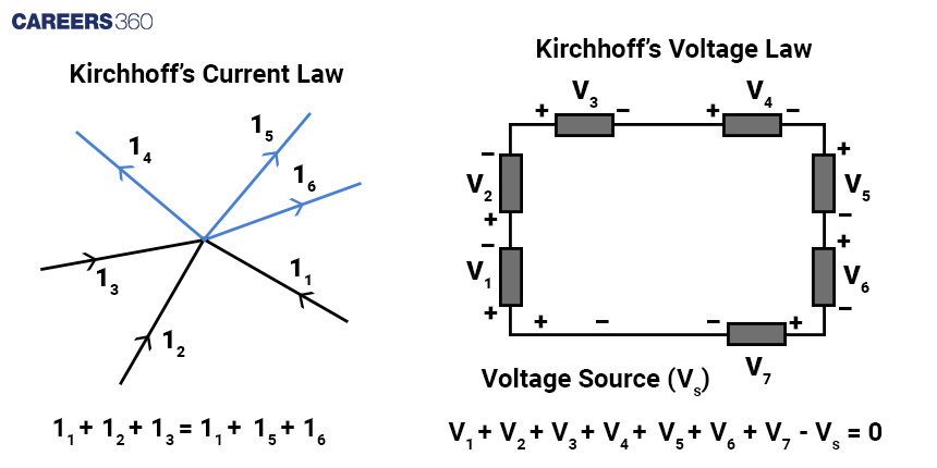
Kirchhoff's Laws are essential tools for analysing complex circuits. These laws are based on the principles of conservation of charge and conservation of energy. Kirchhoff's Current Law (KCL) states that the sum of currents entering a node is equal to the sum of currents leaving that node.
Kirchhoff's Voltage Law (KVL) states that the sum of the voltage drops across a closed loop in a circuit is equal to the sum of the applied voltages.
Analysing Circuits: Series And Parallel
As we dive deeper into circuit analysis, we will learn how to calculate current, voltage, and resistance in various circuit configurations. Let's explore three common configurations:
Series Circuits
In a series circuit, components are connected one after the other in a single path. The same current flows through each component, and the total resistance is equal to the sum of individual resistances. By applying Ohm's Law and Kirchhoff's Laws, we can analyse the behaviour of series circuits. Consider an example as shown below in the image.
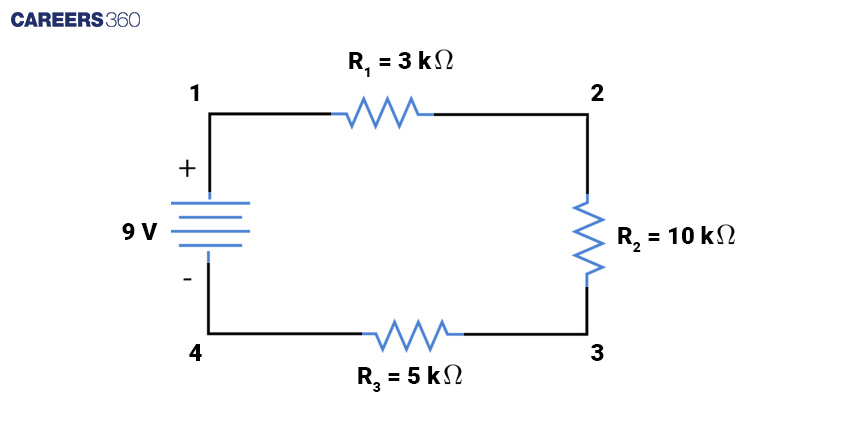
When we move in the path 1→2→3→4. we can observe the same current flow through all the resistances. Therefore this is a series connection of the resistances.
Mathematically we can write the equivalent resistance as a sum of all the resistances.
Thus equivalent resistance = R = R1 + R2 + R3 = 3kΩ + 10kΩ + 5kΩ = 18kΩ
Using Ohm’s law
Current = I = V/R
I = 9V/18kΩ = 0.5mA
Parallel Circuits
In a parallel circuit, components are connected across multiple paths, allowing different amounts of current to flow through each component. The total resistance in a parallel circuit can be calculated using a formula that takes into account the reciprocal of individual resistances. Analysing parallel circuits requires applying Ohm's Law and Kirchhoff's Laws. consider an example as shown below in the image.
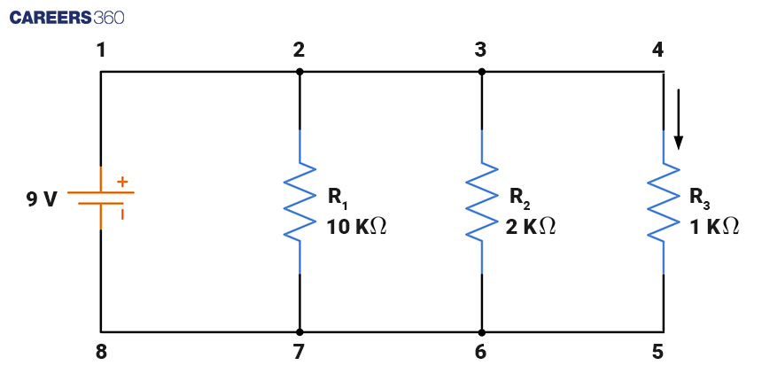
We can observe the voltage difference between the ends of all the resistors is the same. Therefore these are in parallel connection. Equivalent resistance for parallel circuits is given as
1/Req = 1/R1 + 1/R2 + 1/R3...
1/Req = 1/10k + 1/2k + 1/1k
1/Req = 16/10
Req = (10/16)kΩ
Using Ohm’s law
Current I = V/Req = 9/(10/16kΩ) = 144/10 = 14.4mA
Electrical Power
Electrical power is a fundamental concept in the study of electrical circuits. It refers to the rate at which electrical energy is transferred or consumed in a circuit. Power is measured in units called watts (W). Mathematically, power (P) is defined as the product of voltage (V) and current (I), expressed as P = V × I. In this equation, voltage is measured in volts (V), and current is measured in amperes (A). This equation is known as the power formula and is based on Ohm's Law. Power can also be calculated using the formula P = I2R or P = V2R These equations demonstrate that the power consumed or transferred in a circuit increases with the square of the current or voltage, respectively. Additionally, the power decreases as resistance increases.
Consider an example as shown below in the image
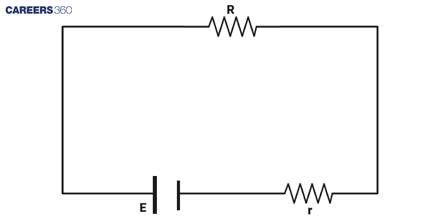
Here E is cell voltage, r is cell resistance and R is the resistance of the circuit.
We want to calculate the relation between the cell resistance(r) and load resistance(R) so that maximum power drowns in the circuit.
We can use mathematical concepts of calculus to calculate the maximum and minimum of any quantity.
We know power is P = I2R
We can observe that resistance R and r are in series therefore equivalent resistance is R+r
Using Ohm’s law
We can calculate current
I = V/R = E/(R+r)
Power = P = [E/(R+r)]2R
For maximum power dP/dR = 0
Using quotient rule of differentiation
y = f(x)/g(x)
dy/dx = [g(x)f'(x)-f(x)g'(x)]/g2(x)
dP/dR = E2[(R+r)2-2(R+r)R]/(R+r)4 = 0
(R+r)[R+r-2R] = 0
R = r
Therefore maximum power can be drawn when internal resistance of a cell is equal to the resistance of the load.
Now you will have a deeper understanding of the mathematics of electrical circuits including the components of circuits such as resistors, capacitors, and inductors, laws of circuits such as Ohm’s law, Kirchhoff's laws, and types of circuits including series and parallel connections.
Also Check | Explore Physics And Unveil The Mysteries Of The Universe While Watching Interstellar
Applications for Admissions are open.
As per latest syllabus. Physics formulas, equations, & laws of class 11 & 12th chapters
JEE Main Important Chemistry formulas
Get nowAs per latest syllabus. Chemistry formulas, equations, & laws of class 11 & 12th chapters
JEE Main high scoring chapters and topics
Get nowAs per latest 2024 syllabus. Study 40% syllabus and score upto 100% marks in JEE
JEE Main Important Mathematics Formulas
Get nowAs per latest syllabus. Maths formulas, equations, & theorems of class 11 & 12th chapters
