

Understanding The Maths Behind Faraday's Law Of Electromagnetic Induction
Faraday's law of electromagnetic induction was formulated by Michael Faraday in the early 19th century. This law has been crucial in understanding the relationship between electricity and magnetism and laid the foundation for modern electrical technology. It is a fundamental principle in physics that describes the relationship between electromagnetic fields and electric currents. It forms the basis for many practical applications, such as power generation, electric motors, and transformers.
In this article, we will delve into the mathematics behind Faraday's Law of Electromagnetic Induction, exploring the mathematical expressions and underlying principles that describe this phenomenon.
Electromagnetic Induction
We will understand this concept through Faraday’s experiment. Faraday's experiment involved a coil of wire placed near a magnet.
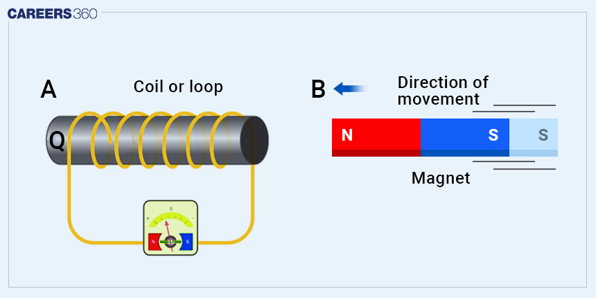
When the magnet moved relative to the coil, he observed a current flow through the circuit. The strength of the induced electromagnetic force (EMF) and resulting current depended on the rate of change of the magnetic field, the number of turns in the coil, and the magnetic field's orientation with respect to the coil. The EMF, also known as voltage, drives electric charges to move in the circuit, creating an electric current.
Mathematics And Faraday's Law Of Electromagnetic Induction
The EMF induced in a closed loop is directly proportional to the negative rate of change of the magnetic flux through the loop.
EMF = ϵ = -dΦ/dt
Where
EMF = ϵ = Electromagnetic force induced in the closed loop (in volts).
dΦ/dt = Rate of change of magnetic flux Φ through the loop with respect to time (In Weber/second or Tesla metres squared per second).
In the case of a closely wound coil of N turns, the change of flux associated with each turn is the same. Therefore, the expression for the total induced emf is given by
ϵ = -N(dΦ/dt)
>>> Magnetic Flux (Φ): Magnetic flux measures the strength of a magnetic field passing through a given area. It is a vector quantity and is represented by the symbol Φ. The magnetic flux through a closed loop is determined by the equation:
ΦB = B × A × cos θ
Where
ΦB = Magnetic field strength (In Tesla).
A = Area of the loop (In square metres).
θ = Angle between the magnetic field lines and the normal vector to the loop's surface.
Suppose the magnetic field strength B remains constant but the coil's area A changes with time t. In that case, the rate of change of magnetic flux (dΦ/dt) can be expressed as
dΦ/dt = B(dA/dt)
Faraday's law can be expressed in an alternate form as follows:
∫E.ds = -d/dt(∫B.dA)
By applying Stokes' theorem in vector calculus, the left-hand side can be written as
∫E.ds = ∫(∇XE).dA
Additionally, note that on the right-hand side
d/dt(∫B.dA) = ∫(dB/dt).dA.
Consequently, we obtain an alternative representation of Faraday's law of induction:
∇XE = -dB/dt
This form is referred to as the differential form of Faraday's law and is one of the four equations in Maxwell's equations, governing all electromagnetic phenomena.
Confused between CGPA and Percentage?
Get your results instantly with our calculator!
Lenz’s Law And Conservation Of Energy
The minus sign in Faraday's law of induction holds significant importance. It indicates that the electromotive force (EMF) generates a current (I) and a magnetic field (B) that act in opposition to the change in flux (Δ), a principle known as Lenz's law. This direction, represented by the negative sign, is so crucial that it is named after the Russian scientist Heinrich Lenz, who independently studied aspects of induction alongside Faraday and Henry.
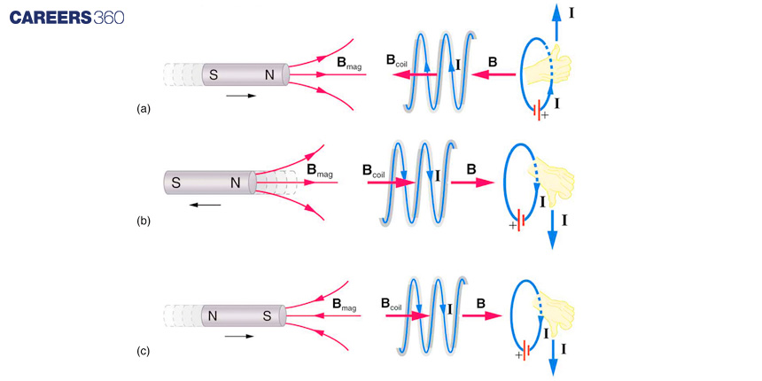
(a) When a bar magnet is thrust into a coil, the magnetic field strength within the coil increases. Consequently, an induced current is generated in the coil, producing a magnetic field in the opposite direction to the bar magnet's field. This opposing effect exemplifies one aspect of Lenz's law, which states that induction always acts to counter any change in flux.
(b) and (c) represent two additional situations. By examining the direction of the induced magnetic field (Bcoil) depicted in these scenarios, one can verify that it indeed opposes the change in flux. Furthermore, the direction of the induced current, determined using the right-hand rule, is consistent with the application of Lenz's Law.
Lenz's law finds its basis in the principle of energy conservation. The induced EMF creates a current that counteracts the change in flux, as a change in flux implies a change in energy.
Applications In Modern Technologies
>>> Electric Generator: Electric generators are devices that transform mechanical energy into electrical energy. They achieve this by generating an electromotive force (EMF) through the rotation of a coil within a magnetic field.
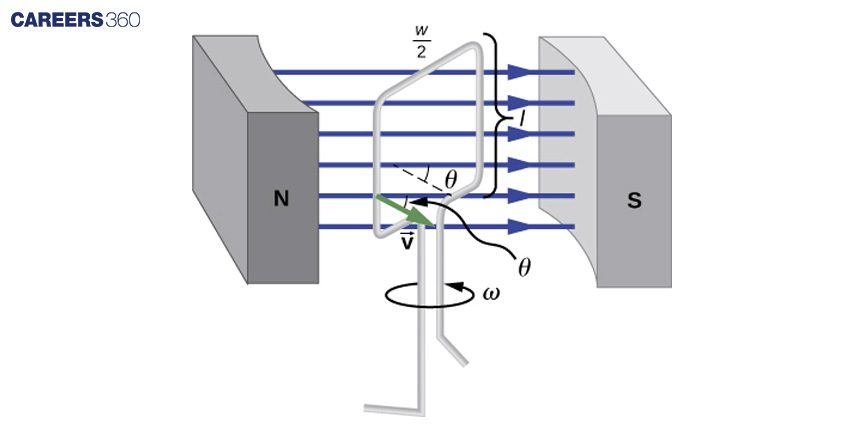
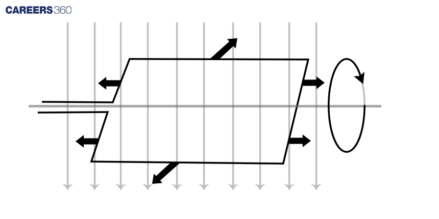
Electric generators operate by converting mechanical energy into electrical energy through the induction of electromotive force (EMF). A single rectangular coil, rotating at a constant angular velocity within a uniform magnetic field, produces an EMF that varies sinusoidally over time. This generator is similar in design to a motor, except in this case, the rotation of the shaft generates a current, unlike a motor where current causes shaft rotation.
The EMF induced on each side of the coil is given by EMF = Bℓv sinθ, and they are in the same direction. The total EMF ε around the loop is then expressed as ε = 2Blv sinθ. However, this expression does not show the time dependence of EMF. To incorporate time dependence, assuming the coil rotates at a constant angular velocity ω, the angle θ is related to angular velocity as θ = ωt.
Therefore, the time-dependent EMF can be represented as ε = 2 Blv sin(ωt). By relating linear velocity v to angular velocity ω as v = rω, where r = w/2 (w is the width of the coil), we can express the EMF as ε = (lw)Bω sin(ωt).
Considering the area of the loop as A = ℓw and accounting for N loops, the EMF induced in a generator coil with N turns and area A rotating at a constant angular velocity in a uniform magnetic field B is given by ε = NABω sin(ωt).
The generators depicted in this context resemble the motors shown earlier, and this similarity is not coincidental. In fact, a motor can function as a generator when its shaft is rotated, demonstrating the reversible nature of these devices.
>>> Electric Motor: An electric motor is a device designed to transform electrical energy into mechanical energy.
The coil experiences forces in opposite directions on its opposite sides due to the movement of charges in opposite directions. This results in the rotation of the coil.
Both motors and generators operate based on a rotating coil within a magnetic field. In generators, the coil is connected to an external circuit and turned, leading to a changing magnetic flux that induces an electromagnetic field. On the other hand, in a motor, a coil carrying an electric current in a magnetic field experiences forces on both sides of the coil, creating a twisting force known as torque, which causes the coil to turn. Any coil carrying current can feel this force when placed in a magnetic field. It is the Lorentz force acting on the moving charges within the conductor. Due to the opposite directions of movement of charges, the forces on the opposite sides of the coil are also in opposite directions, resulting in the rotation of the coil.
