How Many Basic Logic Gates are There
Introduction
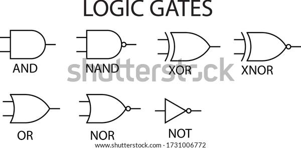
The number of logic gates that we use in digital circuits is seven. Fundamentally, when computers were first designed, the hardware used for even simple calculations was massive. To enable the computers to realize and work according to human instructions, the only way was to use electrical switches. As the electrical switches can exhibit two states, namely ON and OFF, the machine code which the computers understand is also based on two states. The states were denoted as 0 and 1.
With the introduction of transistors and the later ongoing development of electronic devices like Silicon-controlled rectifiers (SCR), thyristor, etc, the sizes of the switches are getting reduced day by day. But the underlying concept of using the ON and OFF states or the logic of switching remains the same. Let's examine it further by diving in.
What are The Types of Logic?
For digital operations, we use the following two types of logic
Positive Logic
It is the set of judgments that are based on the assumption that the high voltage or the high current or the ON state is logically 1 or TRUE, whereas the low voltage or the low current or the OFF state is logically 0 or FALSE.
Negative Logic
It is the set of judgments that are built on the hypothesis that the high voltage or the high current or the ON state is logically 0 or TRUE, whereas the low voltage or the low current or the OFF state is logically 1 or FALSE.
What is a Logic Gate?
The fundamental unit of the digital circuit which implements the logical operation based on the positive or the negative logic and yields the specific output for a certain specified combination of inputs is what you designate as the logic gate.
As the gate at our main entrance controls the passage of persons by remaining open or closed as and when required, the logic gate controls the passage and blockage of signals through it.
The Types of The Logic Gates
The logic gates are categorized on the basis of the operations that they perform on getting the electrical signals as current or voltage at the input terminals. We will refer to the positive logic for discussion of types of basic logic gates. We can get the following seven types of basic logic gates.

The NOT gate
This logic gate has only one input and one output. It reverses the signal that it receives at its input. It yields TRUE output for FALSE input and FALSE output for TRUE input
The AND gate
This logic gate can have two or more inputs but has one output. It results in TRUE output only when all its inputs are TRUE, otherwise, its output is FALSE.
The OR gate
This logic gate can take two or more inputs but has one output. It results in TRUE output only if any one of its inputs is TRUE.
The NAND gate
This logic gate can possess two or more inputs but entertains only one output. It results in FALSE output only when all its inputs are TRUE, otherwise, its output remains TRUE.
The NOR gate
This logic gate can entertain two or more inputs but allows only one output. It results in TRUE output only when all of its inputs are FALSE.
The XOR gate
This logic gate permits only two inputs and a single output. Its output is TRUE only when either of its input is FALSE (or TRUE), otherwise, its output remains FALSE.
The EX-NOR gate
This logic gate agrees to have only two inputs and a single output. Its output is FALSE only when either of its input is FALSE (or TRUE), otherwise, its output remains TRUE.
The Different Uses of The Logic Gates
Here are some of the various uses of basic logic gates
It is useful In the designing of any complex logic circuits.
It is the building block of every digital circuit.
It finds application in the manufacturing of integrated circuits.
It is used in scientific calculators.
It is also employed in the motherboards or the circuit boards of automatic electronic devices.
Conclusion
The ON and OFF states are also designated as HIGH and LOW respectively in positive logic.
The ON and OFF states are also nominated as LOW and HIGH respectively in negative logic.
The AND gate on getting any of its inputs as FALSE produces its output as FALSE. It does not matter even if its 99 inputs are TRUE and only one input is FALSE; it will produce FALSE output.
The OR gate on receiving all its inputs as FALSE produces its output as FALSE. In case it has its 99 inputs as FALSE and only one input is TRUE; it will produce TRUE output.
The NAND gate can be seen as the combination of a NOT gate following the output of an AND gate.
The NOR gate can be visualized as the sequence of a NOT gate following the output of an OR gate.
The XOR gate has its output as FALSE when both its inputs are either FALSE or TRUE, otherwise, its output remains TRUE.
The EX-NOR gate shows TRUE when both its inputs are either FALSE or TRUE, otherwise, its output remains FALSE.
Applications for Admissions are open.
As per latest syllabus. Physics formulas, equations, & laws of class 11 & 12th chapters
JEE Main Important Chemistry formulas
Get nowAs per latest syllabus. Chemistry formulas, equations, & laws of class 11 & 12th chapters
JEE Main high scoring chapters and topics
Get nowAs per latest 2024 syllabus. Study 40% syllabus and score upto 100% marks in JEE
JEE Main Important Mathematics Formulas
Get nowAs per latest syllabus. Maths formulas, equations, & theorems of class 11 & 12th chapters