LCR Circuit - Phasor Diagram, FAQs
Introduction:
LCR circuit is a circuit, consisting of an inductor, a resistor and a capacitor connected in series, where LCR full form is inductance-capacitance-resistance. In this article we will learn about RLC series circuit, phasor diagram of LCR circuit, resonance in LCR circuit and their series circuit diagram.
What is LCR circuit?
Also read :
- NCERT notes Class 12 Physics Chapter 7 Alternating Current
- NCERT solutions for Class 12 Physics Chapter 7 Alternating Current
- NCERT Exemplar Class 12 Physics Solutions Chapter 7 Alternating Current

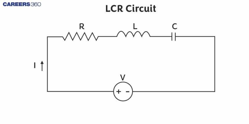
As shown in the LCR circuit diagram, suppose a resistance R, an inductance L and capacitance C are connected in series to a source of alternating emf given by
ε= o sin ωt
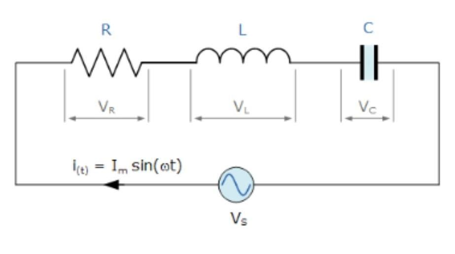
Let I be the current in the series circuit at any instantaneous time. Then
- Voltage VR=RI across the resistance R will be in phase with current I. So phasors VR and I are in same direction. The amplitude of VR is
VOR=IoR
- Voltage VL= XLI across the inductance L is ahead of current I in phase by /2 rad. So phasor VL lies /2 rad anticlockwise w.r.t. the phasorI. Its amplitude is
VOL=IoXL
- Voltage VC= XCI across the capacitance C lags behind the current I in phase by /2 rad. So phasor VC lies /2 clockwise w.r.t. the phasorI. Its amplitude is
VOC=IoXC
As VL and VC are in opposite directions, their resultant is (VL- VC). By parallelogram law, the resultant of Vr and (VL- VC) must be equal to the applied emf given by the diagonal of the parallelogram.
Using Pythagorean Theorem, we get
o2 =(VoR)2 + (VoR- VoC)2
=(IoR)2 + (IoXL- IoXC )2
=Io2 [R2 + (XL- XC )2]
Or
Io=oR2 + (XL- XC )2
Evidently, R2 + (XL- XC )2 is the operational resistance of the series LCR-circuit which opposes or obstructs the flow of current through it and is called impedance of LCR circuit.
Thus
Z= R2 + (XL- XC )2 =R2+(ωL-1ωC)2
The relationship between the resistance R, inductive reactanceXL, capacitive reactance XC and the impedance of RLC circuit Z is shown in Fig. The right angled ∆ OAP is called the impedance triangle.
Also read -
- NCERT Solutions for Class 11 Physics
- NCERT Solutions for Class 12 Physics
- NCERT Solutions for All Subjects
Special Cases
1. When XL> XC, we see from Fig. that emf is ahead of current by phase angle ∅. Hence the phase difference between current and voltage is given by
Tan ∅= XL- XCR or cos∅ =RZ
The immediate current in the circuit will be
I=Iosin(ωt-∅)
The series LCR-circuit is called to be as inductive.
2. When XL < XC or VL < VC, we see from Fig. 7.30. That current is ahead of emf by phase angle ∅ . Phase difference between voltage and current in LCR circuit is given by
Tan ∅ = XC- XLR or cos∅ =RZ
The immediate current in circuit will be
I=Iosin(ωt+∅)
A series LCR-circuit is said to be capacitive.
3. When XL= XC or VL = VC, ∅=0, the emf and current will be in the same phase. The series LCR-circuit said to be purely resistive.
It may also be noted that
Io= oz or Io2= o2Z or Irms=rmsZ
NCERT Physics Notes:
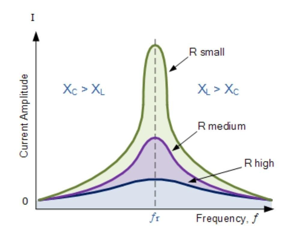
Resonance in series LCR-circuit
A series LCR-circuit is said to be in the resonance condition when the current through it has its maximum value.
The current amplitude Io for a series LCR-circuit is given by
Io=oR2+(ωL-1ωC)2
Clearly, Io becomes zero both for ω→0 and w-ω→∞
The value of Io is maximum when
ωL-1ωC =0 or ω=1LC
Then impedance, Z= R2+(ωL-1ωC)2 =R
Clearly the impedance is minimum. The circuit is purely resistive. The current and voltage are in the same phase and the current in the circuit is maximum. This condition of the LCR-circuit is called resonance condition. The frequency at which the current amplitude Io attains a peak value is called natural or resonant frequency of the LCR-circuit and is denoted by fr
Thus,
r=2πfr=1LC or fr=12πLC
The current amplitude at resonant frequency will be
Io= oR
Related Topics, |
Characteristics of series resonant circuit:
1. Resonance occurs in a series LCR-circuit when XL= XC.
2. Resonant frequency, fr=12πLC
3. The impedance is minimum and purely resistive.
4. The current has a maximum value of (o/ R) at resonant condition.
5. The power dissipated in the circuit is maximum and is equal to rms2R.
6. The current is in phase with the voltage or the power factor is unity (cos∅ = 1 when ∅= 0).
7. Series resonance can occur at all values of resistance R.
8. The voltage across R is equal to the applied emf.
9. The voltages across Land Care equal and have a phase difference of 180° and so their resultant is zero.
10. The voltages across L and C are very high as compared to the applied voltage. Hence a series LCR-circuit is used to obtain a large magnification of a.c. voltage.
11. The series resonant circuit is also called an acceptor circuit. When a number of frequencies are fed to it, it accepts only one frequency fr, and rejects the other frequencies. The current is maximum for this frequency.
Resonance occurs in a series LCR – circuit when XL= XC or r=1LC . For resonance to occur, the presence of both L and C elements in the circuit is essential. Only then the voltages L and C (being 180 out of phase) will cancel each other and current amplitude will be oR i.e., the total source voltage will appear across R. So we cannot have resonance in LR and LC circuits.
Quality factor:
The Q-factor of a series resonant circuit is well-defined as the ratio of the resonant frequency to the change in two frequencies taken on both sides of the resonant frequency such that at every single frequency, the current amplitude develops 12 times the worth at resonant frequency.
Mathematically, the Q-factor can be expressed as
Q=r2-1=r2∆ω=Resonant frequencyBandwidth
Where1and 2, are the frequencies at which the current falls to 12 times its resonant value.
Expression for Q- factor:
Clearly, at r, the impedance is equal to R, while at 1 and 2 its value is √2 R.
Z= R2+(ωL-1ωC)2 =√2 R
Or
R2+(ωL-1ωC)2=2 R2 or ωL-1ωC=±R
We can write
1L-11C = -R – (1)
2L-12C = +R – (2)
Adding (1) and (2), we get
(ω1+2)L-1C(1+ 21 2)=0
Or, 12=1LC
Subtracting (1) from (2), we get
(ω2-1)L+1C(2- 11 2) = 2R
Or,
(ω2-1)(L+1Cω1 2) = 2R
As 12=1LC
So,
2-1=RL
Q=r2∆ω=r1-2=rLR – (3)
The above equation can be written as
Q=rLIrmsRIrms=Voltage drop across L OR CApplied voltage=Voltage magnification
Thus the Q-factor of a series LCR- circuit may also be defined as the ratio of the voltage drop across the inductance (or capacitance) at resonance to the applied voltage.
As r=1LC
Therefore r2=1LC or rL=1rC
Using the above relation, we get
Q=1rCR= 1RLC
If the Q-factor is large that is if R is low or L is large, the bandwidth 2∆ω is small. This means that the resonance is sharp or the series resonant circuit is more selective.
Also check-
Frequently Asked Questions (FAQs)
When the period of applied frequency matches with the natural frequency of a body, the amplitude of vibration becomes maximum. This phenomenon is called resonance.
Forced vibrations are the vibrations in which a body vibrates with a frequency other than its natural frequency under the influence of an external force.
This is since the impedance of the circuit is at its lowest so easily accepts the current whose frequency is equivalent to its resonant frequency.
For high frequency A.C in radio communications, a series resonance circuit is used. LCR circuits are utilized in frequency filter circuits like in high pass filter, low pass filter and band pass filter.
A circuit is supposed to be in resonance when the applied voltage and current are in phase.
Also Read
14 Nov'24 04:14 PM
12 Nov'24 11:48 PM
12 Nov'24 01:28 AM
12 Nov'24 01:13 AM
24 Sep'24 10:48 PM
24 Sep'24 10:24 PM
24 Sep'24 11:34 AM
13 Jun'22 11:48 AM
Articles

Student Community: Where Questions Find Answers