Biot-savart Law
The Biot-Savart Law is one of the fundamental concepts in electromagnetism which describes how magnetic fields are generated. According to Biot-Savart law, "The Magnetic Field at any point in space depends on three factors: density of the current, the distance from the particular current element and the angle between the chosen current element and the point at which we are going to measure the field." This law enables us to appreciate how magnetic fields are created by currents in live wire coils and various conductors.
JEE Main/NEET 2027: Physics Important Formulas for Class 10
NEET 2025: Mock Test Series | Syllabus | High Scoring Topics | PYQs
JEE Main: Study Materials | High Scoring Topics | Preparation Guide
JEE Main: Syllabus | Sample Papers | Mock Tests | PYQs
- Definition of Biot-Savart Law
- The Direction of the Magnetic Field
- 1. The rule of cross product
- Magnetic Field Due to Current in a Straight Wire
- Derivation
- Magnetic Field Due to Circular Current Loop at Its Centre
- Magnetic field due to a current-carrying circular arc
- Special cases
- The Magnetic Field on the Axis of the Circular Current-Carrying Loop
- Solved Examples Based on Biot-Savart Law
Thus, the practical significance of the Biot-Savart Law includes the use of calculation of magnetic fields of motors, generators, and inductors all of which use a controlled magnetic field to work properly. This article discusses a detail of the Biot-Savart Law, when it should be used and in detail offers several examples of its use.

Definition of Biot-Savart Law
"The Biot-Savart Law states that the magnetic field
The mathematical expression for the Biot-Savart Law is:
where:
-
-
-
-
-
-
The Biot-Savart Law helps to calculate the magnetic field produced by any shape of a current-carrying conductor.
If a point charge q is kept at rest near a current-carrying wire, It is found that no force acts on the charge. It means a current-carrying wire does not produce an electric field. However, if the charge q is projected in the direction of the current with velocity v, then it is deflected towards the wire (q is assumed positive). There must be a field at P that exerts a force on the charge when it is projected, but not when it is kept at rest. This field is different from the electric field which always exerts a force on a charged particle whether it is at rest or in motion. This new field is called the magnetic field and is denoted by the symbol B. The force exerted by a magnetic field is called magnetic force.

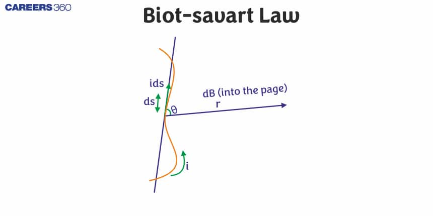
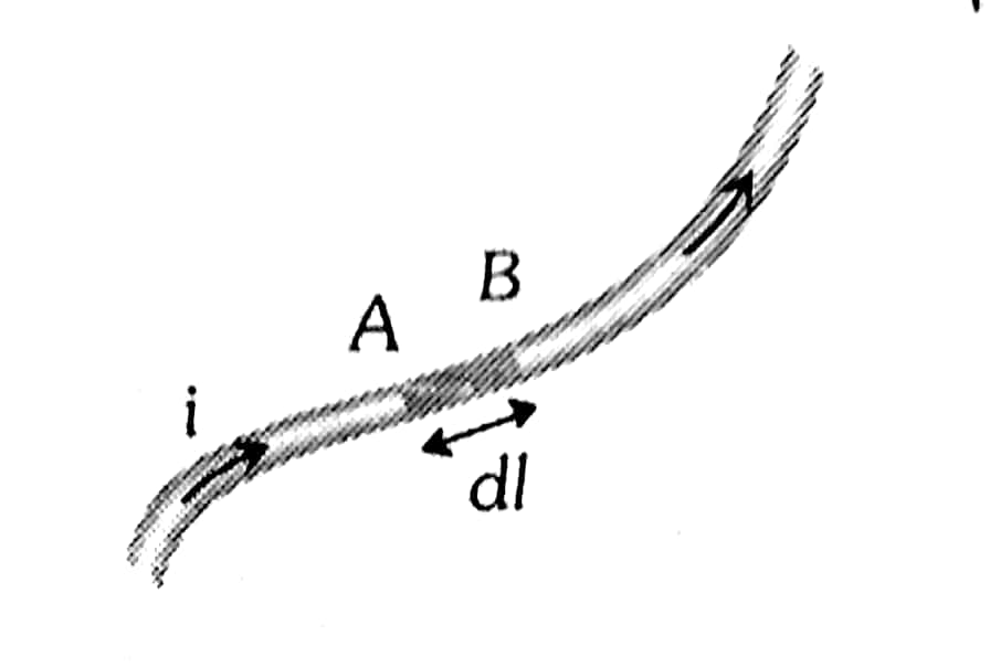
According to Biot Savart's Law, the magnetic induction dB at point P due to the elemental wire segment AB as shown in the figure depends upon four factors which are given as
(i) dB is directly proportional to the current in the element.
(ii) dB is directly proportional to the length of the element
(iii) dB is inversely proportional to the square of the distance r of the point P from the element
Combining the above factors, we have
Where K is a proportionality constant and its value depends upon the nature of the medium surrounding the current carrying wire. Its SI Units its value is given as
Here, i is the current,
The magnetic field at a point
Vector form:
Scalar form:
For medium other than vacuum,
Where:
The Direction of the Magnetic Field
1. The rule of cross product
The direction of the field is perpendicular to the plane containing the current element and the point
2. Right-hand thumb rule
The direction of this magnetic induction is given by the right-hand thumb rule stated as "Hold the current carrying conductor in the palm of the right hand so that the thumb points in the direction of the flow of current, then the direction in which the fingers curl, gives the direction of magnetic field lines"

Cases:

Case 1. If the current is in a clockwise direction then the direction of the magnetic field is away from the observer or perpendicular inwards.

Case 2. If the current is in an anti-clockwise direction then the direction of the magnetic field is towards the observer or perpendicular outwards

Magnetic Field Due to Current in a Straight Wire
Magnetic field lines around a current-carrying straight wire are concentric circles whose centre lies on the wire.

The magnitude of magnetic field B, produced by a straight current-carrying wire at a given point is directly proportional to the current I pairing through the wire i.e. B is inversely proportional to the distance 'r' from the wire \left(B \propto \frac{1}{r}\right) as shown in the figure given below.

Derivation
The directions of magnetic fields due to all current elements are the same in the figure shown, we can integrate the expression of magnitude as given by Biot-Savart law for the small current element dy as shown in the figure

In order to evaluate this integral in terms of angle
Substituting in the integral, we have :
Taking out I and r out of the integral as they are constant:
Integrating between angle
Note:
Magnetic field due to a current-carrying wire at a point P which lies at a perpendicular distance r from the wire, as shown, is given as:

From figure,
Hence, it can be also written as
Different Cases
Case 1: When the linear conductor XY is of finite length and the point P lies on its perpendicular bisector as shown

Case 2: When the linear conductor XY is of infinite length and the point P lies near the centre of the conductor

Case 3: When the linear conductor is of semi-infinite length and the point P lies near the end Y or X

Case 4: When point P lies on the axial position of the current-carrying conductor then the magnetic field at P,

Note:
- The value of magnetic field induction at a point, on the centre of separation of two linear parallel conductors carrying equal currents in the same direction, is zero.
- If the direction of the current in the straight wire the known then the direction of the magnetic field produced by a straight wire carrying current is obtained by Maxwell's right-hand thumb rule.
Magnetic Field Due to Circular Current Loop at Its Centre
Magnetic Field due to circular coil at Centre

Consider a circular coil of radius a and carrying current I in the direction shown in Figure. Suppose the loop lies in the plane of the paper. It is desired to find the magnetic field at the centre O of the coil. Suppose the entire circular coil is divided into a large number of current elements, each of length dl.
According to Biot-Savart law, the magnetic field
where
The direction of
For each current element, angle between
For N turns,
where N=number of turns, i= current and r=radius of a circular coil.
Magnetic field due to a current-carrying circular arc
Case 1: Arc subtends angle theta at the centre as shown below then

Proof:

Consider length element dl lying always perpendicular to
Using the Biot-Savart law, the magnetic field produced at
Equation (1) gives the magnitude of the field. The direction of the field is given by the right-hand rule. Thus, the direction of each of the dB is into the plane of the paper. The total field at O is
The angle subtended by element
where the angle
Case 2: Arc subtends angle

Case 3:The magnetic field of the Semicircular arc at the centre is

Case 4: Magnetic field due to three-quarter Semicircular Current-Carrying arc at the centre

Special cases
1. If the Distribution of current across the diameter then

2. If Current between any two points on the circumference then

3. Concentric co-planar circular loops carrying the same current in the Same Direction-

If the direction of currents are the same in concentric circles but have a different number of turns then
4. Concentric co-planar circular loops carrying the same current in the opposite Direction

If the number of turns is not the same i.e
5. Concentric loops but their planes are perpendicular to each other

\text { Then } B_{\text {net }}=\sqrt{B_1^2+B_2{ }^2}
6. Concentric loops but their planes are at an angle ϴ with each other

The Magnetic Field on the Axis of the Circular Current-Carrying Loop
In the below figure, it is shown that a circular loop of radius R carries a current
the current in the segment
Another symetric
Due to symmetry the components of
The x -components of the

We can use the law of Biot-Savart to find the magnetic field at point P on the axis of the loop, which is at a distance x from the centre.
The magnetic field due to the current element is
Since
the magnitude
The components of the vector
Everything in this expression except
The integral
So, we get
- If x>>R, then
- At centre ,
Recommended Topic Video
Solved Examples Based on Biot-Savart Law
Example 1: The direction of current in a current element
1) As that of current in the wire
2) Opposite the direction of current in the wire
3) It's a scalar quantity
4) Always circular
Solution:
Current Element
It is the product of the current and length of the infinitesimal segment of the current wire.
wherein
The current element is a vector quantity, and the direction is the same as the current in the wire.
Example 2: Unit (S.I.) of the current element
1) Ampere
2) Ampere metre
3) Newton
4) Tesla
Solution:
The current element
S.I. unit is
Hence, the answer is option (2).
Example 3: A current I flow in an infinitely long wire cross-section in the form of a semicircular ring of radius R. The magnitude of the magnetic field induction along its axis is:
1)
2)
3)
4)
Solution:
Magnetic field due to Current Element

Net magnetic field
Example 4: A straight section PQ of a circuit lies along the X-axis from
1) Proportional to a
2) Proportional to
3) Proportional to
4) Zero
Solution:
Magnetic field due to Current Element
If
wherein
Thus field at a point on the line of wire is zero.

The magnetic field at a point on the axis of a current-carrying wire is always zero.
Example 5: An arc of a circle of radius
1)
2)
3)
4)
Solution:
Hence, the answer is option (2)
Frequently Asked Questions (FAQs)
Also Read
02 Jul'25 08:06 PM
02 Jul'25 08:05 PM
02 Jul'25 08:05 PM
02 Jul'25 08:04 PM
02 Jul'25 08:01 PM
02 Jul'25 06:23 PM
02 Jul'25 05:55 PM
02 Jul'25 05:55 PM
02 Jul'25 05:55 PM
02 Jul'25 05:54 PM
Articles

Student Community: Where Questions Find Answers