1. State two advantages of AC over DC.
The first advantage is that AC is easy to transfer over long distances, while DC can not be transferred over a very long distance. Another advantage is that in AC, the flow of electric current changes its direction forward and backwards periodically, while in DC, it flows in a single direction steadily and AC is less expensive and easy to generate than DC.
2. Define inductor.
The coil which stores magnetic energy in the form of a magnetic field is known as an inductor. So, we can say that it is a device which stores magnetic energy.
3. What is the SI unit of inductance and capacitance?
The SI unit of inductance is Henry and it is denoted by the symbol H. The SI unit of capacitance is Farad and it is denoted by the symbol F.
4. State two disadvantages of alternating current.
Alternating current is dangerous at high voltages and requires insulation. Another disadvantage is that batteries or cells can not be directly charged from the ac source.
5. Name some sources of DC and AC.
Sources of DC are voltaic cells, dry cells and DC generators. Sources of AC are hydroelectric generators, nuclear power generators and thermal power generators.
6. How does inductive reactance change with frequency, and why?
Inductive reactance increases as frequency increases. This is because inductors oppose changes in current, and higher frequencies mean more rapid current changes. The formula for inductive reactance is XL = 2πfL, where f is frequency and L is inductance, showing the direct relationship between reactance and frequency.
7. How do AC motors work, and what is the significance of the rotating magnetic field?
AC motors work by creating a rotating magnetic field in the stator, which interacts with the rotor to produce torque. The rotating field is created by the phase differences in AC currents flowing through multiple stator windings. This principle allows AC motors to start and run without additional starting mechanisms, unlike many DC motors.
8. How do AC circuit breakers differ from DC circuit breakers?
AC circuit breakers must deal with the zero-crossing of the current waveform, which can make arc extinction easier but also requires faster response times. They often use the natural zero-crossing to interrupt the current. DC circuit breakers, on the other hand, must actively create a current zero to extinguish the arc, often using more complex mechanisms.
9. What is the significance of harmonics in AC circuits?
Harmonics are integer multiples of the fundamental frequency in AC circuits. They can be caused by non-linear loads and can lead to increased power losses, overheating, and interference with other equipment. Harmonics can also cause resonance issues and reduce the overall power quality of the system.
10. How does the concept of impedance matching apply to AC circuits?
Impedance matching in AC circuits involves adjusting the source and load impedances to maximize power transfer or minimize signal reflection. It's crucial in applications like radio frequency circuits, audio systems, and power transmission. Proper impedance matching ensures efficient energy transfer and minimizes signal distortion.
11. Why is AC preferred over DC for long-distance power transmission?
AC is preferred for long-distance power transmission because it can be easily transformed to higher or lower voltages using transformers. Higher voltages result in lower current for the same power, which reduces power losses in transmission lines. DC, on the other hand, cannot be easily transformed, making it less efficient for long-distance transmission.
12. How does skin effect impact AC circuits, especially at high frequencies?
Skin effect is the tendency of AC to flow near the surface of a conductor, effectively reducing the usable cross-sectional area. This effect becomes more pronounced at higher frequencies, increasing the effective resistance of the conductor. It's particularly important in high-frequency applications and can necessitate the use of specialized conductors to minimize power losses.
13. What is power factor in AC circuits and why is it important?
Power factor is the ratio of real power to apparent power in an AC circuit. It ranges from 0 to 1 and indicates how efficiently electrical power is being used. A higher power factor (closer to 1) means more efficient power use. It's important because low power factors can lead to increased energy costs, higher current draw, and reduced system capacity.
14. What is the resonance frequency in an AC circuit, and why is it significant?
The resonance frequency is the frequency at which inductive and capacitive reactances in an AC circuit are equal and cancel each other out. At this frequency, the circuit's impedance is purely resistive, leading to maximum current flow. Resonance is significant in filter design, tuning circuits, and can cause dangerous voltage or current spikes if not properly managed.
15. How do transformers work in AC circuits, and why don't they work with DC?
Transformers work in AC circuits by electromagnetic induction. They use changing magnetic fields produced by AC in the primary coil to induce voltage in the secondary coil. Transformers don't work with DC because DC produces a constant magnetic field, which doesn't induce voltage in the secondary coil. The changing magnetic field is crucial for the transformer's operation.
16. What is the principle behind AC capacitive voltage dividers, and how do they differ from resistive dividers?
AC capacitive voltage dividers use the reactive properties of capacitors to divide voltage. Unlike resistive dividers, they don't dissipate power as heat. The voltage division depends on the capacitive reactance, which varies with frequency. This makes them useful in high-frequency applications and where power loss must be minimized.
17. What is the significance of the power triangle in AC circuit analysis?
The power triangle is a graphical representation of the relationship between real power, reactive power, and apparent power in AC circuits. It helps visualize how these power components relate to each other and to the power factor. The right angle of the triangle represents the 90-degree phase difference between real and reactive power.
18. How do AC circuit protection devices like Ground Fault Circuit Interrupters (GFCIs) work?
GFCIs work by monitoring the current balance between the hot and neutral wires in an AC circuit. If there's an imbalance (indicating a ground fault), the GFCI quickly interrupts the circuit. This protection is crucial for preventing electric shocks in areas where water might be present, like bathrooms and kitchens.
19. How does mutual inductance affect AC circuits with coupled inductors?
Mutual inductance in AC circuits with coupled inductors leads to induced voltages in one inductor due to changing current in another. This can either add to or subtract from the self-inductance effect, depending on the relative orientation of the inductors. Mutual inductance is crucial in transformer operation and can significantly impact the behavior of AC circuits with multiple inductive components.
20. What is the significance of the Ferranti effect in AC power transmission lines?
The Ferranti effect is the rise in voltage at the receiving end of a long, lightly loaded AC transmission line. It occurs due to the line's distributed capacitance and inductance. This effect can lead to overvoltage conditions and must be considered in the design and operation of long-distance power transmission systems.
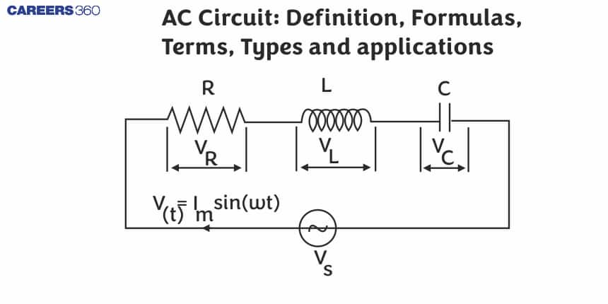
21. What is an AC circuit and how does it differ from a DC circuit?
An AC circuit is an electrical circuit that operates with alternating current (AC), where the flow of electric charge periodically reverses direction. This differs from a DC circuit, which uses direct current that flows in only one direction. In AC circuits, voltage and current vary sinusoidally with time, while in DC circuits, they remain constant.
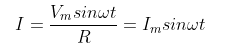
22. What is the phase difference between voltage and current in a purely resistive AC circuit?
In a purely resistive AC circuit, there is no phase difference between voltage and current. They reach their maximum, minimum, and zero values simultaneously. This is because resistors do not store energy in electric or magnetic fields, unlike capacitors and inductors.
23. What is the purpose of a phase-shifting transformer in AC systems?
A phase-shifting transformer is used to control the phase angle between the input and output voltages in AC systems. This is useful for managing power flow in electrical grids, improving system stability, and controlling the direction of power flow between interconnected systems. It allows for fine-tuning of power distribution without changing voltage magnitudes.
24. How do AC voltage regulators work and why are they necessary?
AC voltage regulators maintain a constant voltage level despite fluctuations in input voltage or load. They typically use transformers with multiple taps or electronic switching to adjust the output voltage. Voltage regulation is necessary to protect sensitive equipment from voltage variations and ensure consistent performance of electrical devices.
25. How does power factor correction work in AC circuits?
Power factor correction aims to bring the power factor closer to unity by compensating for reactive power. This is typically done by adding capacitors in parallel with inductive loads. The capacitors provide the reactive power needed by the inductive loads, reducing the reactive power drawn from the source and improving overall system efficiency.
26. What is the significance of frequency in AC circuits?
Frequency in AC circuits represents the number of complete cycles of voltage or current that occur per second. It is typically measured in Hertz (Hz). Frequency is crucial because it affects the behavior of circuit components, power transmission efficiency, and the design of electrical devices. Most household AC systems operate at either 50 Hz or 60 Hz.
27. What is the RMS (Root Mean Square) value in AC circuits and how does it relate to peak values?
The RMS value in AC circuits is the equivalent steady DC value that would produce the same heating effect. For a sinusoidal waveform, the RMS value is approximately 0.707 times the peak value. RMS values are important because they provide a meaningful average for AC quantities that oscillate between positive and negative values.
28. What is the significance of the j-operator in AC circuit calculations?
The j-operator (where j = √-1) is used in AC circuit analysis to represent the 90-degree phase shift associated with reactive components. It allows complex impedances to be expressed in the form R + jX, where R is resistance and X is reactance. This notation simplifies calculations involving phase differences and complex circuit elements.
29. What is the difference between real power, reactive power, and apparent power in AC circuits?
Real power (measured in watts) is the power actually consumed or utilized in the circuit. Reactive power (measured in volt-amperes reactive or VAR) is the power that oscillates between the source and the load due to energy storage in reactive components. Apparent power (measured in volt-amperes or VA) is the vector sum of real and reactive power and represents the total power in the circuit.
30. What is the skin depth in AC circuits and how does it affect conductor design?
Skin depth is the depth below the surface of a conductor at which current density has decreased to 1/e (about 37%) of its value at the surface. It decreases with increasing frequency, leading to higher effective resistance. In high-frequency applications, conductors are often designed as hollow tubes or Litz wires to mitigate skin effect and reduce power losses.
31. How do inductors and capacitors behave differently in AC circuits compared to DC circuits?
In DC circuits, inductors act like short circuits after steady state is reached, while capacitors act like open circuits. In AC circuits, inductors oppose changes in current, creating inductive reactance, while capacitors oppose changes in voltage, creating capacitive reactance. These behaviors lead to phase shifts between voltage and current in AC circuits.
32. How does impedance differ from resistance in AC circuits?
Impedance is a more comprehensive measure of opposition to current flow in AC circuits, while resistance only accounts for the opposition in DC circuits. Impedance includes both resistance and reactance, which is the opposition to current due to inductance and capacitance. Unlike resistance, impedance can vary with frequency in AC circuits.
33. How do series and parallel AC circuits differ from their DC counterparts?
While the basic principles of series and parallel connections remain the same, AC circuits introduce the concept of phase relationships. In AC series circuits, voltages across components may not simply add up due to phase differences. In parallel AC circuits, current division depends not just on impedance magnitudes but also on their phase relationships.
34. What is a phasor diagram and how is it useful in analyzing AC circuits?
A phasor diagram is a graphical representation of the magnitude and phase relationships between voltages and currents in an AC circuit. It uses rotating vectors (phasors) to represent sinusoidal quantities. Phasor diagrams are useful for visualizing and calculating phase relationships, making complex circuit analysis more intuitive and manageable.
35. How does capacitive reactance change with frequency, and why?
Capacitive reactance decreases as frequency increases. This is because capacitors oppose changes in voltage, and higher frequencies mean more rapid voltage changes. The formula for capacitive reactance is Xc = 1 / (2πfC), where f is frequency and C is capacitance, showing the inverse relationship between reactance and frequency.
36. What is the principle behind AC induction heating, and what are its applications?
AC induction heating uses electromagnetic induction to heat conductive materials. High-frequency AC in a coil creates a rapidly changing magnetic field, inducing eddy currents in the material to be heated. This principle is used in industrial processes like metal forging, cooking (induction stoves), and even some medical treatments.
37. What is the significance of the Q factor in AC resonant circuits?
The Q factor (quality factor) in resonant circuits is a measure of the sharpness of resonance. A higher Q factor indicates a narrower bandwidth and lower energy loss. It's important in filter design, oscillators, and tuned circuits. The Q factor affects the selectivity and efficiency of resonant systems.
38. How do AC-DC converters (rectifiers) work, and what are the differences between half-wave and full-wave rectification?
AC-DC converters change AC to DC using diodes to allow current flow in only one direction. Half-wave rectification uses one diode, converting only half of the AC wave, resulting in pulsating DC. Full-wave rectification uses four diodes (bridge rectifier) or a center-tapped transformer with two diodes, converting both halves of the AC wave, resulting in smoother DC output with less ripple.
39. What is the purpose of a neutral wire in AC power systems?
The neutral wire in AC power systems provides a return path for current in single-phase systems and balances loads in three-phase systems. It's typically connected to ground at the distribution transformer or service entrance. The neutral wire helps maintain a stable voltage reference and allows for the use of both 120V and 240V in residential systems (in countries using 120/240V split-phase).
40. How do AC generators (alternators) produce alternating current?
AC generators produce alternating current by rotating a magnetic field (rotor) inside a stationary set of conductors (stator). As the magnetic field rotates, it induces a sinusoidal voltage in the stator windings due to electromagnetic induction. The frequency of the AC produced is directly related to the rotational speed of the generator and the number of magnetic poles.
41. How do AC synchronous motors maintain a constant speed, and what is the significance of the pull-in torque?
AC synchronous motors maintain a constant speed by locking the rotor's magnetic field to the stator's rotating field. The pull-in torque is the maximum torque the motor can develop to pull into synchronism with the supply frequency. Once synchronized, the motor speed remains constant regardless of load variations within its capacity.
42. What is the principle behind AC current transformers, and how do they differ from voltage transformers?
AC current transformers (CTs) work on the principle of electromagnetic induction to step down high currents to measurable levels. Unlike voltage transformers, CTs are connected in series with the circuit and have their secondary winding essentially short-circuited through a low-impedance ammeter or relay. They are designed to maintain a constant current ratio rather than a voltage ratio.
43. How does corona discharge affect high-voltage AC transmission lines?
Corona discharge is the ionization of air surrounding high-voltage conductors. In AC transmission lines, it leads to power losses, audible noise, radio interference, and can cause long-term degradation of insulation materials. The effect is more pronounced at higher voltages and is influenced by conductor geometry, weather conditions, and air pollution levels.
44. What is the significance of the Steinmetz equivalent circuit in analyzing AC induction motors?
The Steinmetz equivalent circuit is a simplified model used to analyze AC induction motors. It represents the motor's electrical characteristics, including stator and rotor resistances and reactances, and the magnetizing branch. This model helps in calculating motor performance parameters like efficiency, power factor, and torque-speed characteristics under various operating conditions.
45. How do AC variable frequency drives (VFDs) control motor speed, and what are their advantages?
AC VFDs control motor speed by varying the frequency and voltage supplied to the motor. They typically rectify AC to DC and then use an inverter to create AC of the desired frequency. Advantages include energy savings, precise speed control, soft starting capabilities, and reduced mechanical stress on the motor and driven equipment.
46. What is the principle behind AC electromagnetic flow meters, and why are they suitable for conductive fluids?
AC electromagnetic flow meters work on Faraday's law of electromagnetic induction. They create a magnetic field perpendicular to the flow of a conductive fluid, inducing a voltage proportional to the flow velocity. They are suitable for conductive fluids because the fluid acts as the conductor moving through the magnetic field, allowing for non-invasive flow measurement.
47. How do AC power line communication systems work, and what are their challenges?
AC power line communication systems use existing power lines to transmit data by superimposing a modulated carrier signal on the power waveform. Challenges include dealing with noise from electrical devices, signal attenuation over distance, and variations in network topology. These systems must also ensure that communication signals don't interfere with power delivery or other services.
48. What is the significance of the slip frequency in AC induction motors?
Slip frequency in AC induction motors is the difference between the synchronous speed of the stator's magnetic field and the actual rotor speed. It's crucial for torque production – without slip, there would be no induced currents in the rotor and thus no torque. The slip frequency also indicates the motor's loading condition and efficiency.
49. How do AC superconducting fault current limiters work, and what are their advantages in power systems?
AC superconducting fault current limiters use the property of superconductors to


 is V_{R}=IR
  and it is in phase with the current.
 and it leads the current by an angle of 90 degrees.
 and it lags the current by an angle of 90 degrees.